• The move to the new server is done. There are some software and database maintenance updates in process. This has us passing the hat around to help out. We appreciate any donations. Seriously, even a dollar helps. The payment page may be found here - https://www.audiokarma.org/support.html

Choke input experiments

Brice

AK Subscriber
Subscriber
Hi guys,

I wanted to share some measurements I've made with a choke input supply.

The test conditions were as follow:

- Same amplifier (Allen Organ) with a 500 VCT -> dual 5AR4 rectifiers -> choke -> 250 uF -> B+.
- Same tubes and test methodology.
- Line kept at 120 VAC in all cases.
- Power RMS on a 4 ohm load: 1 4 6.25 12.25 25 36 49 56.25 64 Watts.

I used 3 different chokes:
- The original Air Design little choke: 6H 86 R.
- Military potted choke: 8H 120R (approximated).
- Military potted choke: 12H 142R.

I ran the identical power test for each of them and recorded the B+ voltage drop and the B+ ripple with a True RMS Fluke DVM.

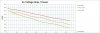
Here are the 2 graphs I've got:
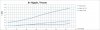
PSRipple.jpg PSVDrop.jpg

So at first the voltage drop seems a function of the internal resistance of the PS, mostly the choke, the rectifiers and the PT impedance and it is quite linear. But the drop is quite important.

And the ripple is interesting as non linear, and of course the bigger the choke is the lower the ripple becomes.
But still, it is much more than I thought.

Understood that a continuous 64 watts power it straining the PS quite a bit, my load resistor was getting toasty.

Have you guys done similar testing of choke input PS under stress and found similar results?

Thanks
Brice.
 
Register to hide this ad
Just to clarify - was the resistive load on the B+, or on the amplifier output?

Do you have any load current ratings on those chokes? At 70W, the 13H choke will have circa 180mAdc and a resistive loss of circa 4.4W, whereas the 6H will have circa 170mAdc and a resistive loss of circa 2.5W.

Have you measured the transformer effective resistance and compared results to the 5AR4 datasheet for circa 170-180mAdc load? That loading shouldn't be straining the 5AR4 for choke input as long as the choke impedance is high enough (ie. inductance hasn't sagged too much).

Were you going to do a PSUD2 simulation to see how well those measurements can be estimated during design?

That B+ ripple may be more noticeable in an Allan 75 as it is UL PP, rather than just PP, but those amps use global feedback so whether this then becomes a noticeable contributor to speaker hum is probably a difficult set of measurements to make.
 
The 4 R was on the amplifier output load.

Yes both military chokes were rated for .25 A. The original Allen choke is unknown.

So you mean the DC resistance of the PT?

I simulated this PS with LTSpice. The results are not close to the real world so I most likely made mistakes.

It is not a 75 model but the C-3, a 6L6 PPP with fixed screen voltage.
The amplifier is very silent to my ears so there is no hum/noise issue.

I just had the feeling that the original choke was too small and wanted to experiment with a bigger one.
This leading to that and I now have a better view of the effect various chokes have on a choke input PS but I am surprised at the results.
 
The 5AR4 Amperex datasheet shows the way to calculate Rt from PT primary and secondary (and choke DCR) resistances. PSUD2 allows that effective PT resistance to be included in its simulation, as it influences the 5AR4 peak current level.

What was the test frequency used for the amplifier to generate the plotted amp output power values? Would the B+ voltmeter have a frequency response that covers the test frequency? The B+ ripple may include some test frequency ripple contribution.

I can't recall if you found a schematic for the C-3? I guess it just goes to show how little influence the power supply has on an amplifier with negative feedback.

It's always great to see some test results :rockon:
 
Thanks. I used 120 R PT resistance, 60 per side and I think this is close to reality.

I did all test a 1 Khz. Interesting. I did not think about it.
My Fluke 117 is 2.0% + 3 (DC, 45 Hz to 500 Hz) 4.0% + 3 (500 Hz to 1 kHz). So am still good, just by luck :)
That amp has a measured -13.7 db feedback.

For sure with the military chokes I would be able to add more capacitance after it, should help.
And with actual playing music, I would not be able to handle this amp at full blast, so I don't reach this level of sag and ripple anyway.

I was just surprised how much ripple and sag I was getting with choke input and 250 uf caps.
And I don't want to add another RC or LC stage as then the sag will be even more pronounced.

I never spent too much time in this type of measurement under full load, although it wasn't clipping yet.
It was a fun test.

Agreed it's nice to see actual measurement results.

Thank you.
 
The power supply current will be more than the B+ voltage and speaker output power, due to losses in the output stage (output transformer resistances, output valves).

The sag in B+ is I think predominantly the effective R of the power transformer and choke, and the increasing power supply feed current - ie. the B+ filter capacitor doesn't have as much influence, except on ripple. The effective resistance of the power transformer is calculated from one half of the secondary (60 ohm), but given you have a high secondary/primary voltage ratio (n), the total could approach 120 ohm. Although more Rt increases sag, it has a secondary benefit of lowering ripple (both at 120Hz and higher frequencies). And inspection of the 5AR4 datasheet shows just how much less sag you would basically achieve compared to a capacitor input power supply configuration.

I'd think 1kHz is high enough not to introduce much rms ripple on your capacitor, due to capacitor impedance probably approaching ESR level, so the measured B+ ripple is likely just from 120Hz.

The IM performance is likely not as good as a modern amp, and that may be an issue with modulating power supply ripple on to a signal - so not audible as 'hum', but perhaps a soft form of signal distortion, so the lower the ripple level and its harmonics perhaps the better in that regard.

Good to hear it was fun, as testing can become onerous.
 
on the tube amp power supplies I have added a choke, have also seen a 6-9db reduction in power supply noise.

If you run a spectrum plot you can visually see and measure the improvement.

nice work on the Allen organ amp. They usually have some nice iron on them.
 
This is one of the reasons I tend to build Class A.

With an AB amp, current goes up with power output, and you have rectifier and resistive losses. Now the LC filter does a better job of keeping the RMS current increasing linearly with actual drawn DC. Not so much of a surprise, but if it is, look at the current wave forms.

IME, once you get power output over about 20W, it becomes hard to tell the difference between 20 and 50W.
cheers,
Douglas
 
Choke input power supplies can be very useful. In particular, it can be possible to reduce a supply by about 100V by going from a cap input to a choke input. In the case of a SE amp that can run both 2A3 and 300B, I can simply connect an input cap to the PS and thereby take a 400V 300B supply down to 300V for a 2A3. I have a pair of mono-block amps that I use in this way. They employ a 2.3H @ 150mA, 60r DCR choke.

But here's the difference in my amps compared to your test setup: the DCR of the chokes is far less. For my big amps I attempt to find chokes with a DCR of about 45r. Now in general these are big heavy chokes with lots of iron and copper. They also have lower inductance which helps keep the reactance of the power supply low while also providing good ripple reduction. One typical choke is a Collins 678 0534 009. It has 1.9H @ 800mA and more inductance at lower currents and a DCR of 45r. I mention this choke in particular because it is fairly common on auction and I have bought a few. I see them from $20 to $75, so be patient and buy right. There is also a similar choke that is common because it was used on a Heathkit transmitter, so many were sold. So with a 45 DCR choke I can put two in series and still have the same power supply resistance of your best performing supply while maintaining excellent ripple rejection because of the LCLC supply.

Finally, I should mention that I generally use two 6AX4GTB rectifiers or one 5V3A/5AU4: I can't see the point in using $75 NOS Mullard 5AR4s when better alternatives are far cheaper.
 
You guys are absolutely right.
If your B+ is too high, switching to a choke input is a way to go, as long as you pick the right choke of course.

Low DCR is better for sagging, and high inductance is also good for ripples, but this make the choke huge and I don't have much room on that chassis, 3 inches is what I can fit.

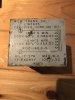
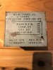
Here is the pics of the 2 chokes I've used.
 

Attachments

  • s-l1600 (1).jpg
    s-l1600 (1).jpg
    94.4 KB · Views: 27
  • s-l1600.jpg
    s-l1600.jpg
    99.4 KB · Views: 27
I have done more tests today.

I compared the amp noise with the original choke and one of the military one, no signal applied.
I was thinking maybe the B+ ripple could be visible in the amp's output signal despite the PP cancelling effect.

Well no. I did not see any change in output signal with both chokes.
Still the 1.7 mV noise but no change.

So this confirms that on a well PP build amp the PS noise will well cancelled.
 
A search for COLLINS CHOKE on your favorite auction site can reveal some real winners; but they are big and heavy.

Right now there is a 2H @ 750mA with 20r DCR; a 3H @ 500mA with a 25r DCR; and a 4H @ 300mA with a 40r DCR

Good stuff; but not cheap.....
 
Thank you.

Yes I saw them, very nice but too big as replacement.

And now I know why choke input PS is not used as much anymore: the cost/size of a good choke is quite high versus cap input PS.
 
Back
Top Bottom