• The move to the new server is done. There are some software and database maintenance updates in process. This has us passing the hat around to help out. We appreciate any donations. Seriously, even a dollar helps. The payment page may be found here - https://www.audiokarma.org/support.html

Circuit calculation question- fun challenge - 1060 diff input amp

tranguru

Active Member
Hi team,

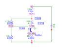
I tried to calculated the theoretical voltages to expect on the 1060 diff amp.

but I was not able to do so:
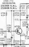
1705244090929.png

I don't know how to calculate the voltages such as the 14v between r707 and r709.
Any thoughts ?
Vcc = 60v

I am quite sure I need Ie in H701 emitter resistance = 26mV/Ie - but what is the value of Ie?

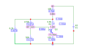
I was able to simulate it in Microcap circuit calculation tool. and I noticed that the transistor type (beta) plays a key role those 14V you see on the diagram vary quite a bit from 9 to 16v in microcap depending on the transistor model.
For those who have microcap : I had to add the model for 2sc945 to microcap.
For those who don't have it - it is free now and works great!

I thought that might a fun challenge to pose to the group here :)
I love doing this because it forces me to fully understand how a circuit works.
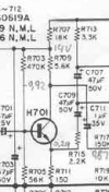
 

Attachments

  • 1705243807863.png
    1705243807863.png
    32.1 KB · Views: 14
Register to hide this ad
Forgive me for the obtuse question, but I am so used to seeing a long tail pair as the diff amp that I am having some difficulty identifying it on this circuit.

Is the feedback through the emitter of H701?
 
It is not a differential stage but yes, there is feedback at the emitter of H701.
but is plays the same role as a diff amp - that is why I called the 1060 diff amp.

I guess that is the way they cut costs - rather than a true diff amp with transistor+diode/zener based current source in the tail like in the 510
1705389869897.png

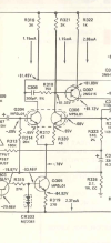
Here I know how to calculate the circuit... as the current in r319 is easy to calculate more or less.
 
Last edited:
R759 should be 8.2K, not 6.2k
Diff pair is a topology. I think you should be calling it the input stage.
Differential pair is normally found on DC coupled amplifiers.
In this circuit, your biggest variable is the hfe of the transistor, but with (relatively) low values of R707and 759 reduces the effects of wide range of hfe.
After you correct R759, see how much changes yiou get with different transistor models.
 
R759 should be 8.2K, not 6.2k
Diff pair is a topology. I think you should be calling it the input stage.
Differential pair is normally found on DC coupled amplifiers.
In this circuit, your biggest variable is the hfe of the transistor, but with (relatively) low values of R707and 759 reduces the effects of wide range of hfe.
After you correct R759, see how much changes yiou get with different transistor models.
Thanks for the feedback!! need new glasses :)

1705410928406.png


not much change.
Maybe my 2SC945 spice model is not correct - I found it on a forum - Microcap did not have it.
 
Why did you change R709 from 5.6k to 3.9k in your model?
Good catch, but you'll find that the currents don't change, and the only difference will be the voltage at the collector of the transistor.
An observation - the 14 volts and 60 volts are someone else's measurement - not the specification. So should be taken with grain of salt. It seems to me that the lower the hfe, the higher the other voltages will be, but not by much. (no I haven't run any simulations.)
 
When designing a circuit like this one, we try to have the voltage at the collector of the transistor at 50% of the supply voltage, at the junction of R707 and R759. The reason is to have symetrical clipping and less distortion. So, the value of R709 is important. We can adjust the current in the transistor by R703, or find a transistor that has the good hFE for a fixed value of R703 to meet that objective.
 
Great catch indeed

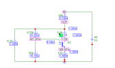
here is the new simulation:
1705432500652.png
Steve: as you mentioned - not much change.

I will re--open up the 1060 I have the bench and measure - this weekend.
 
What hFE has your transistor in your model? The original transistor has 200. Since the collector voltage on your model is very low I suspect that you have a transistor with too much gain.
 
Here is the model I got on a web page
.model 2sc945 npn
IS=3.577E-14 BF=2.382E+02 NF=1.01 VAF=1.206E+02 IKF=3.332E-01 ISE=3.038E-16 NE=1.205 BR=1.289E+01 NR=1.015 VAR=1.533E+01 IKR=2.037E-01 ISC=3.972E-14 NC=1.115 RB=3.680E+01 IRB=1.004E-04 RBM=1 RE=8.338E-01 RC=1.557E+00 CJE=1.877E-11 VJE=7.211E-01 MJE=3.486E-01 TF=4.149E-10 XTF=1.000E+02 VTF=9.956 ITF=5.118E-01 CJC=6.876p VJC=3.645E-01 MJC=3.074E-01 TR=5.145E-08 XTB=1.5 EG=1.11 XTI=3 FC=0.5 Vceo=50 Icrating=100m MFG=NEC

Beta = BF = 238. - I think

This is the Gummel-Poon simulation model
 
I see. I never work with simulators. In my first calculus I neglected the current in R703 because it is of the order of 1% of the current in R707. Since the resistors have 5% tolerance it was acceptable in first approximation. When I take into account the base current of the transistor, this circuit works best with the 2sc945R gain class (90-180). With the 2sc945Q gain class (135-270), the collector voltage is low. With an hFE of 112, and Vbe of 0.65V, the collector voltage falls exactly at 50% of the voltage at R759.
 
The measurements on the scan are quite close to what I measured in the amp.
But the Vcc= 74V

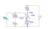
I reduced the Beta to 200

I get
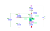
1705610062758.png


so getting closer.
 
Back
Top Bottom