• The move to the new server is done. There are some software and database maintenance updates in process. This has us passing the hat around to help out. We appreciate any donations. Seriously, even a dollar helps. The payment page may be found here - https://www.audiokarma.org/support.html

Citation II bias switch

James Cox

AK Subscriber
Subscriber
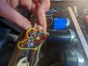
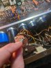
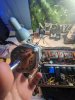
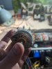
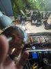
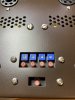
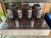
So I've got myself into a bit of a jam and hoping someone here may be able to help me out. My citation ii recently had a bit of a meltdown while I was attempting to set the bias on my tubes while switch from triode back to ultra linear. The first 2 tubes biased no problem but when I switch to the 3rd tube there was a catastrophic failure involving quite a few blown resistors, including the internal resistor for the meter, and a few flames shooting out of the bias switch. I immediately unplugged the amp and the flames went out instantly but the damage had already been done. I switched out all the blown resistors but 2 of the contacts on the bias switch have completely burned up. After talking to Jim Mcshane it seems like replacements aren't readily available but he said I would need a 2 deck 7 position switch. I found one that's a bit bigger than original but I can get it to fit if I reposition a few resistors. The problem I'm having though is I can't seem to wrap my head around how to wire the new switch compared to the original. There are quite a few more connections on the replacement I found than the original part. Or if anyone happens to have a spare bias switch or knows how to possibly repair the burnt out contacts I'm all ears! Here's some pics of the original switch and replacement.
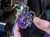
PXL_20230208_193930409.jpg PXL_20230208_163119313.jpg PXL_20230208_163108264.jpg PXL_20230208_163056035.jpg PXL_20230208_163029346.jpg
 

Attachments

  • PXL_20230208_163036435.jpg
    PXL_20230208_163036435.jpg
    109.6 KB · Views: 10
Register to hide this ad
I'd get rid of the switch and the meter, similar to what I did to my Citation V which now has ability for adjustable bias. In the case of the Citation II all you have to do is install jacks for an external, light years more accurate, meter.
 

Attachments

  • IMG_1416.JPG
    IMG_1416.JPG
    148.5 KB · Views: 35
  • IMG_1483.JPG
    IMG_1483.JPG
    136.3 KB · Views: 34
original switch is one wafer with two sets of contacts right? Looks like one set of fingers on each side of the wafer.

Looks like the replacement is two wafers, each with one set of contacts, so total number is the same, they're just spread apart by 1/2" or so

have to identify the common terminals on the new wafer. Looks like on the original, one is red, can't tell what the other is. Once you have the commons identified, it should just be a matter of moving the wires over to the new switch. Maybe set both fully CCW and confirm which terminal is connected to the common so they move over in the right order.
 
I'd get rid of the switch and the meter, similar to what I did to my Citation V which now has ability for adjustable bias. In the case of the Citation II all you have to do is install jacks for an external, light years more accurate, meter.
So after a long few months I'm finally ready to dig into this project. Could you give me more info on how you rewired the amp to bypass the switch and meter and what parts you used for the jacks and bias pots? I really want to get this back up and running as soon as possible
 
I would suggest that you keep it original if possible. Is the indexing the same on the replacement switch? 36º and 30º are both common. Also, is the new switch the same type (break before make, continuous, etc.)? Maybe you could post a photo of the contact side. If it's a valid replacement, wiring shouldn't be difficult.

Jack
 
In my post above, related to the Citation V--I used that as an example of possibly what could be done to a Citation II. However, in the case of a Citation II if it had a working selector switch but not a meter, the meter could easily be removed and two probe points installed so the bias could be measured by an external multi meter.

If the switch and the meter are shot, yes, you could wholesale rip it all out and do something similar that I did with the Cit V but it would probably require a different board size but very similar circuit to allow bias checks and adjustments.
 
Your solution is excellent for Citations with broken meters. I don't think that's the case here, but I could be wrong. I just wouldn't change the format if the meter can be saved, due to the loss of resale value. Jim McShane no longer has replacements for the Cit V but maybe he has a meter for the Cit II (I haven't asked).

This thread points out yet again why members should include their location when they join. I don't understand why forums don't at least recommend this in the sign-up procedure. There might be someone local to the OP who could provide hands-on help with this.

Jack
 
I couldn't find a switch that fit properly. One is way too small and the other is too big. The meter and switch both blew at the same time. I replaced the resistor in the meter and believe it's ok but not sure what to do about the switch. I'm located in Huntington WV, pretty much audio no man's land haha
 
I couldn't find a switch that fit properly. One is way too small and the other is too big. The meter and switch both blew at the same time. I replaced the resistor in the meter and believe it's ok but not sure what to do about the switch. I'm located in Huntington WV, pretty much audio no man's land haha
Can you clarify this a little - How did you know what value to replace the resistor with? Is the meter still working?

Jack
 
I looked up some info online and found a thread where someone mentioned a 330 ohm resistor being the proper replacement. I believe the meter is working but haven't been able to test it since the switch is blown. I checked it with a meter and it measured around 330ohm now instead of open like it was before I replaced the resistor.
 
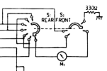
I see that the Cit II metering switch is drawn incorrectly in the factory schematic. Your photo shows a long contact on the 7-position track (spoke?) of the rear section, but that's drawn as a short contact in the print. I can't see the front side of the wafer in your photos, but is the 330Ω resistor to ground also connected to a long contact?

Screen Shot 2023-07-13 at 2.54.41 PM.png

Jack
 
Edited: In case you didn't know, connecting an ohmmeter directly across a sensitive panel meter can damage it. You might try adding a 5KΩ series resistor temporarily to see if the meter flickers when you use the ohmmeter. I would just be concerned that the meter might be open at this point. If so, and if there's no replacement meter available, no sense pursuing a replacement switch.
 
Last edited:
Oh I didn't realize they were that sensitive. Its been quite awhile since I first started working on this so I'll have to double check the meter when I break it out tomorrow.
 
It's been 2 years but I have an update! 2 of the contacts were burned out on the original switch and I managed to replace those 2 contacts with 2 out of the replacement switch. Everything works as it should now!
 
It's been 2 years but I have an update! 2 of the contacts were burned out on the original switch and I managed to replace those 2 contacts with 2 out of the replacement switch. Everything works as it should now!
Do you mean that you removed the contacts from one switch and installed them on the other? Can you describe the process? I have a switch in need of a similar repair.
 
That's exactly what I did! If you scroll back through the thread you'll see pics of the original switch and the replacement i bought that was too big. I carefully removed the original broken contacts. Depending on how your switch is made you may need to use a dremel tool but mine came off using a small screwdriver to pry and some wire snips. After those were removed I used a dremel tool to remove the contacts from the replacement switch. It took a lot of trial and error but luckily there were plenty of contacts to practice on. I think I ended up tossing around 5 that broke during the process. Once those were removed and I had two good ones I used.very tiny machine screws to attach them to the original switch. I wish I would've taken some pics during the process.
 
Back
Top Bottom