• The move to the new server is done. There are some software and database maintenance updates in process. This has us passing the hat around to help out. We appreciate any donations. Seriously, even a dollar helps. The payment page may be found here - https://www.audiokarma.org/support.html

CJ PV5 Questions

captouch

Addicted Member
I just re-acquired a PV5 that I think is stock.

I had a Bill Thalmann upgraded PV5 10+yrs ago that I sold in the spirit of not holding onto gear I wasn’t using. It was a distinct unit that had a full chrome cover vs the usual textured black cover. It was one of the only pieces that I have since regretted selling because it’s a classic and there’s something to be said for that warm smooth sound, even if it’s not one’s main preamp. Being able to rotate in a PV5 as a change up is a treat.

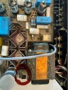
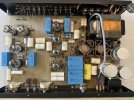
Fast forward to today, I acquired what I think is a stock PV5 with original can caps in the PS. Pic attached.

So far all I’ve done is re-seat all tubes in case they got loose during shipping, and measured the 3 can caps and the 22uF and 10uF electrolytic caps with a simple cap meter (I think I missed the muting circuit cap). All are close to the spec range, which is good and made me feel secure enough to power it up and play with it for awhile, though I’ll eventually replace them since these are 40yrs old or so.

It plays well, no noisy controls. A bit of tube noise, but the seller was nice enough to leave all vintage tubes in the unit, so may just need to rotate through to see whether I have quieter tubes in my stash.

Because my previous unit was already upgraded, I never got to hear one stock. So enjoying hearing a stock unit for the first time. Going into a McIntosh MC2255 and outputting through some Sonus Faber Concerto Homes.

I know there’s been some threads from @Crang recently on upgrading his unit with helpful input from @arts and others. I’ll be reading through those as I think about upgrading or replacing aged parts to make it more reliable.

But for now, just sharing my new purchase.

Edit: I actually did have a question when I started this thread, but found an answer as I was writing it, thus the thread title. Sorry about that - no clickbait intended.
 

Attachments
  • IMG_1572.jpeg
    IMG_1572.jpeg
    143.4 KB · Views: 56
Last edited:
Register to hide this ad
I just re-acquired a PV5 that I think is stock.

I had a Bill Thalmann upgraded PV5 10+yrs ago that I sold in the spirit of not holding onto gear I wasn’t using. It was a distinct unit that had a full chrome cover vs the usual textured black cover. It was one of the only pieces that I have since regretted selling because it’s a classic and there’s something to be said for that warm smooth sound, even if it’s not one’s main preamp. Being able to rotate in a PV5 as a change up is a treat.

Fast forward to today, I acquired what I think is a stock PV5 with original can caps in the PS. Pic attached.

So far all I’ve done is re-seat all tubes in case they got loose during shipping, and measured the 3 can caps and the 22uF and 10uF electrolytic caps with a simple cap meter (I think I missed the muting circuit cap). All are close to the spec range, which is good and made me feel secure enough to power it up and play with it for awhile, though I’ll eventually replace them since these are 40yrs old or so.

It plays well, no noisy controls. A bit of tube noise, but the seller was nice enough to leave all vintage tubes in the unit, so may just need to rotate through to see whether I have quieter tubes in my stash.

Because my previous unit was already upgraded, I never got to hear one stock. So enjoying hearing a stock unit for the first time. Going into a McIntosh MC2255 and outputting through some Sonus Faber Concerto Homes.

I know there’s been some threads from @Crang recently on upgrading his unit with helpful input from @arts and others. I’ll be reading through those as I think about upgrading or replacing aged parts to make it more reliable.

But for now, just sharing my new purchase.

Wow! Congrats!

Short of getting out my magnifying glass just to be sure, that is totally original, right down to the Ty-Rap holding the power switch cable to the filter cap.

That has GOT to be a low mileage unit if (and it certainly appears to be) the heater filter cap is still the original; usually, either that filter shorts out and kills the rectifier in the process, or vice versa. Very rare to see either one still functioning...

I strongly recommend replacing all of the electrolytics, especially the cans, and uprating the heater rectifier and it's heatsink, just for safety's sake. These are well known failure points due to heat, ripple and marginal ratings, and can easily cost you the power transformer. Other than that, so long as the controls and tube sockets are quiet, I'd just enjoy it as-is :)


Edit;

The only other change that I would advocate would be to replace the output coupling caps in the Phono and Line stages. Those are the four blue ERO 2µ2/250V boxes.
Considering the quality of the other custom for CJ polystyrene coupling caps used in these units, I've never understood why they cheaped out on these...

This is my go-to (formerly ERO, now owned by Vishay) for a really top quality replacement; The MKP1839 (NOT 1839HQ, which is an internally series connected capacitor)

 
Last edited:
Wow! Congrats!

Short of getting out my magnifying glass just to be sure, that is totally original, right down to the Ty-Rap holding the power switch cable to the filter cap.

That has GOT to be a low mileage unit if (and it certainly appears to be) the heater filter cap is still the original; usually, either that filter shorts out and kills the rectifier in the process, or vice versa. Very rare to see either one still functioning...

I strongly recommend replacing all of the electrolytics, especially the cans, and uprating the heater rectifier and it's heatsink, just for safety's sake. These are well known failure points due to heat, ripple and marginal ratings, and can easily cost you the power transformer. Other than that, so long as the controls and tube sockets are quiet, I'd just enjoy it as-is :)


Edit;

The only other change that I would advocate would be to replace the output coupling caps in the Phono and Line stages. Those are the four blue ERO 2µ2/250V boxes.
Considering the quality of the other custom for CJ polystyrene coupling caps used in these units, I've never understood why they cheaped out on these...

This is my go-to (formerly ERO, now owned by Vishay) for a really top quality replacement; The MKP1839 (NOT 1839HQ, which is an internally series connected capacitor)

Thanks arts!

The heater cap is labeled “TVLU 1095 3500-5000uF 250VDC” and it currently measures 5300uF.

The PS caps are labeled “TVLU 1750 60-90uF 500VDC“ and they measure about 110uF each.

Based on the other thread, you recommended “Any high-quality, 105°C rated electrolytics from a reputable manufacturer. . .low ESR for the HV section, something with a higher ripple current rating for the heater supply”.

Replacing a multi-tab can cap with a modern electrolytic which is much smaller, do you have any example parts that would fit well and look reasonable aesthetically? Do I really need to hit the original 500V spec for the PS caps?

Regarding the heater rectifier, it’s the part highlighted in red in the attached pic, right? Is there a particular rectifier and heat sink you’d recommend?

The D1-D4 rectifier diodes are okay as is?

The output coupling caps you recommended will still preserve the nice warm sound, but just provide some additional clarity?

I guess I have a bunch of questions after all. . Thanks so much arts.
 

Attachments

  • IMG_1573.jpeg
    IMG_1573.jpeg
    138.2 KB · Views: 24
I wouldn't put any faith in measuring the capacitance value of an old electrolytic, as this value often rises due to problems with other quality parameters, giving a false sense of security. The only "safe" test for an old cap (in my old mind at least, haha) is testing leakage current at rated voltage. And even then, leakage often rises dramatically with temperature rise.

Frankly, regardless of how well these caps measure, I would NOT trust them.


Those old TVLU caps really gave quite the tolerance range, eh? But I think you typo'd the heater cap, the voltage was spec'd at 25V.

Personally, for the heater cap I'd go with 4700µF/35V or perhaps a bit higher. Capacitance higher just because manufacturers cheap out on the tolerance these days, and the voltage just for a bit more safety margin.

For the HV caps, the voltage is proper as spec'd, so I'd go with either 100µf/500V or 120µF/500V.

Don't go crazy high on capacitance values, as this provides no benefit here and just needlessly stresses the power XMFR.

Offhand, I can't recommend any capacitor part numbers, you'll have to go looking. Shouldn't be too hard to fit something new, as everything they sell now is much smaller.


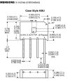
The heater rectifier is indeed the thing in the red circle. I'd recommend something in the KBU8 series, as it fits right in and has an 8A rating. 100V or higher will do.
Original heatsink is marginal, but you're on your own finding an upgrade, as all of mine came from a local surplus supplier.

I usually replace the HV rectifiers with UF5408.

The original ERO caps (not the later Vishay types, which spec very differently, despite having the same part number) were not great. I use the MKP1839 in my own PV5.
I feel they provide an improvement over the originals.
 
I wouldn't put any faith in measuring the capacitance value of an old electrolytic, as this value often rises due to problems with other quality parameters, giving a false sense of security. The only "safe" test for an old cap (in my old mind at least, haha) is testing leakage current at rated voltage. And even then, leakage often rises dramatically with temperature rise.

Frankly, regardless of how well these caps measure, I would NOT trust them.


Those old TVLU caps really gave quite the tolerance range, eh? But I think you typo'd the heater cap, the voltage was spec'd at 25V.

Personally, for the heater cap I'd go with 4700µF/35V or perhaps a bit higher. Capacitance higher just because manufacturers cheap out on the tolerance these days, and the voltage just for a bit more safety margin.

For the HV caps, the voltage is proper as spec'd, so I'd go with either 100µf/500V or 120µF/500V.

Don't go crazy high on capacitance values, as this provides no benefit here and just needlessly stresses the power XMFR.

Offhand, I can't recommend any capacitor part numbers, you'll have to go looking. Shouldn't be too hard to fit something new, as everything they sell now is much smaller.


The heater rectifier is indeed the thing in the red circle. I'd recommend something in the KBU8 series, as it fits right in and has an 8A rating. 100V or higher will do.
Original heatsink is marginal, but you're on your own finding an upgrade, as all of mine came from a local surplus supplier.

I usually replace the HV rectifiers with UF5408.

The original ERO caps (not the later Vishay types, which spec very differently, despite having the same part number) were not great. I use the MKP1839 in my own PV5.
I feel they provide an improvement over the originals.

Spent some time with your guidance and came up with the BOM below:

Coupling cap upgrades:
MKP1839522405 x 4 - Vishay Film Capacitors 2.2uF 400volts 10%

PS Rectifier Diode Upgrade:
UF5408-E3/54 x 4 - Vishay Rectifiers Vr/1000V Io/3A

Heater Cap Upgrade:
478CKE035M - Cornell Dubilier Aluminum Electrolytic Capacitor Radial Leaded 4700uF 35V 20% (2.34A ripple current)

PS Caps Upgrade:
500LXW100MEFR18X45 x 2 - Rubycon Radial Leaded GENERAL PURPOSE ELECTROLYTIC CAPACITORS (no ESR specs I can see - not a lot of radial leaded choices at 500V rating)

Heater Rectifier Upgrade:
KBU8G-E4/51 - Vishay Bridge Rectifiers 8.0 Amp 400 Volt

Heat sink for Heater Rectifier:
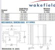
677-15ABPE - Wakefield Thermal Heat Sinks Heat Sink for Vertical Mount for TO220/TO247/TO218/15-LEAD MULTIWATT, 38.1mm H

The KBU rectifier package is kind of wide 23.7mm, so the heat sink I selected is 25.4mm wide to accommodate, but it has those two board pins which I doubt will work. Nor will the holes align.

So I need to put more work in to find a heat sink that will work with that package.

Other than the heat sink, I think everything else above should work.
 

Attachments

  • IMG_1576.jpeg
    IMG_1576.jpeg
    86.3 KB · Views: 4
  • IMG_1577.jpeg
    IMG_1577.jpeg
    95.2 KB · Views: 4
Spent some time with your guidance and came up with the BOM below:

Coupling cap upgrades:
MKP1839522405 x 4 - Vishay Film Capacitors 2.2uF 400volts 10%

PS Rectifier Diode Upgrade:
UF5408-E3/54 x 4 - Vishay Rectifiers Vr/1000V Io/3A

Heater Cap Upgrade:
478CKE035M - Cornell Dubilier Aluminum Electrolytic Capacitor Radial Leaded 4700uF 35V 20% (2.34A ripple current)

PS Caps Upgrade:
500LXW100MEFR18X45 x 2 - Rubycon Radial Leaded GENERAL PURPOSE ELECTROLYTIC CAPACITORS (no ESR specs I can see - not a lot of radial leaded choices at 500V rating)

Heater Rectifier Upgrade:
KBU8G-E4/51 - Vishay Bridge Rectifiers 8.0 Amp 400 Volt

Heat sink for Heater Rectifier:
677-15ABPE - Wakefield Thermal Heat Sinks Heat Sink for Vertical Mount for TO220/TO247/TO218/15-LEAD MULTIWATT, 38.1mm H

The KBU rectifier package is kind of wide 23.7mm, so the heat sink I selected is 25.4mm wide to accommodate, but it has those two board pins which I doubt will work. Nor will the holes align.

So I need to put more work in to find a heat sink that will work with that package.

Other than the heat sink, I think everything else above should work.
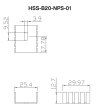
I can be kind of air-headed dense, but I found a heat sink that will work after looking more at pics of how the rectifier and heat sink are oriented on the board.

I think the attached should work.

Also, read from @Crang ’s thread that the UF5408’s are 3A and a bit of a challenge to fit. Not sure if I’ll take the challenge to shape the leads with those or default to UF4007’s.

Also added the other electrolytic caps to the BOM. Think I’m about ready to order.

@arts when you work on these, do you just leave the transformer attached to the bottom cover and rotate the cover as needed with all wires intact to access the area of the bottom board needed?

When I had my old one, that’s what I recall doing, but I only had to replace a single electrolytic on the edge of the board. This work will require more components to be replaced.

Just wanted to be sure I was following best practices.

Thanks again for all your guidance.
 

Attachments

  • IMG_1579.jpeg
    IMG_1579.jpeg
    39.9 KB · Views: 7
I have owned both versions of the PV5 (stock and upgraded). The upgraded is different but some of the musicality of the original is not there. If it were me, I would be more inclined to install new lytics in the power supply and listen to that for a while before I went the all film cap route. you also may want to remove those transistors, clean them and apply fresh heat sink compound before reinstalling. They do run warm.
 
I have owned both versions of the PV5 (stock and upgraded). The upgraded is different but some of the musicality of the original is not there. If it were me, I would be more inclined to install new lytics in the power supply and listen to that for a while before I went the all film cap route. you also may want to remove those transistors, clean them and apply fresh heat sink compound before reinstalling. They do run warm.

Thanks!

The effect on sound is really just the 4 coupling caps in the signal path, right? The rectifier, diodes, and other electrolytics aren’t really going to affect sound, will they?

Great point on the transistors. I can easily do that.

One of the things I always wondered about my previous, already modified, PV5 was how close to the classic sound (that everyone loved initially) it really was. This stock unit is great in the sense I can start totally stock, make it safe/reliable, and go incrementally from there. The more time consuming work will be doing the big caps since there are multiple large tabs to unsolder.

By the time I finish everything else, the four coupling caps should be relatively easy work. It makes sense to leave those for last and have a good long listen with the stock ones before swapping them for the modern ones.
 
Thanks!

The effect on sound is really just the 4 coupling caps in the signal path, right? The rectifier, diodes, and other electrolytics aren’t really going to affect sound, will they?

Great point on the transistors. I can easily do that.

One of the things I always wondered about my previous, already modified, PV5 was how close to the classic sound (that everyone loved initially) it really was. This stock unit is great in the sense I can start totally stock, make it safe/reliable, and go incrementally from there. The more time consuming work will be doing the big caps since there are multiple large tabs to unsolder.

By the time I finish everything else, the four coupling caps should be relatively easy work. It makes sense to leave those for last and have a good long listen with the stock ones before swapping them for the modern ones.
if you replace the lytics in the power supply with film, the bass impact may not be as great. Yes the coupling caps will make a significant difference.
Key thing to consider is how far removed do you want to get from the original sound of the PV5?
If you are looking at coupling caps the Jupiter copper foil caps are really organic sounding.
 
Thread update:

Got my parts in and updated the 3 can caps, four 1N4007 diodes to UF4007, the bridge rectifier + small heat sink to the recommended 8A rectifier and larger heat sink, and the 22uf/50V and 47uF/25V.

Have the four coupling caps @arts recommended, but will listen (now safely with new power supply and heater caps) with the stock coupling caps before putting in the Vishays.

I thought I had messed things up as I was getting really low level scratchy sound first time after starting things up. Got quite a scare when the relay clicked in after a minute or so and music blared out.

It looks like the only non-original thing on this unit was the relay cap. It must have failed (or someone was impatient and wanted a shorter mute time), and someone had put a 10uF/100V in place of the 47uF stock cap. So when I first got it and listened to it, I was used to the shorter mute time.

Didn’t remember that the standard start up muting time is over 1 minute.
 

Attachments

  • IMG_1616.jpeg
    IMG_1616.jpeg
    137.1 KB · Views: 18
Thread update:

Got my parts in and updated the 3 can caps, four 1N4007 diodes to UF4007, the bridge rectifier + small heat sink to the recommended 8A rectifier and larger heat sink, and the 22uf/50V and 47uF/25V.

Have the four coupling caps @arts recommended, but will listen (now safely with new power supply and heater caps) with the stock coupling caps before putting in the Vishays.

I thought I had messed things up as I was getting really low level scratchy sound first time after starting things up. Got quite a scare when the relay clicked in after a minute or so and music blared out.

It looks like the only non-original thing on this unit was the relay cap. It must have failed (or someone was impatient and wanted a shorter mute time), and someone had put a 10uF/100V in place of the 47uF stock cap. So when I first got it and listened to it, I was used to the shorter mute time.

Didn’t remember that the standard start up muting time is over 1 minute.
Did you ever put the vishay coupling caps in? I have a bone stock PV5 with just electrolytics and timing relay replaced. Have been wondering about swapping out the ERO couplers also but I am very happy with how everything sounds.
 
Did you ever put the vishay coupling caps in? I have a bone stock PV5 with just electrolytics and timing relay replaced. Have been wondering about swapping out the ERO couplers also but I am very happy with how everything sounds.

Excellent question, and I don’t remember!

Not too long after I recapped it, I went through a whole cycle of rotating through new speakers and eventually changed them, added two subs, and am using a miniDSP Flex with corrective PEQ curves to compensate for room issues.

All that being said, I very recently reinserted it in the signal chain to see if it colored the sound in a pleasing way.

Listening to Quadrophenia now. When this is done, I’ll check. But I have a feeling I did put them in.
 
Excellent question, and I don’t remember!

Not too long after I recapped it, I went through a whole cycle of rotating through new speakers and eventually changed them, added two subs, and am using a miniDSP Flex with corrective PEQ curves to compensate for room issues.

All that being said, I very recently reinserted it in the signal chain to see if it colored the sound in a pleasing way.

Listening to Quadrophenia now. When this is done, I’ll check. But I have a feeling I did put them in.

Yes, confirmed they’re in.
 
Excellent question, and I don’t remember!

Not too long after I recapped it, I went through a whole cycle of rotating through new speakers and eventually changed them, added two subs, and am using a miniDSP Flex with corrective PEQ curves to compensate for room issues.

All that being said, I very recently reinserted it in the signal chain to see if it colored the sound in a pleasing way.

Listening to Quadrophenia now. When this is done, I’ll check. But I have a feeling I did put them in.
Nice!! Thank you!
 
Back
Top Bottom