• The move to the new server is done. There are some software and database maintenance updates in process. This has us passing the hat around to help out. We appreciate any donations. Seriously, even a dollar helps. The payment page may be found here - https://www.audiokarma.org/support.html

Cleanest most Audiophile way to reduce preamp output by 10db

Big_T

Member
What would, be the cleanest most pure way to reduce the output gain from my EAR 834P Phono stage (clone) from about 50db (seems to be the consensus on the output) to about 40db? So a reduction of about 10db.

I’m fine with adding a high quality volume pot at the output sections but was wondering if using a resistor or some other combination would be a more clean and pure way to reduce the output.


Also I already tried putting in 5751 tubes all three positions as well as various combinations. It did not reduce the gain by more than about a 1/3 of a db in any combination. I tested the output recording test tones and music (12ax7 to 5751). It really didn’t change the volume output in any usable way even with all three positions holding 5751 tubes. It did make it a bit more bright sounding with less bass so I guess there is that.
 
Register to hide this ad
Use of an inline attenuator at the output requires knowing several additional specifications. First, what is the minimum load for the EAR that won't affect RIAA EQ, and how does that compare with the input impedance of the attenuator? Second, what is the output impedance of the attenuator? Finally, how will the attenuator be loaded, and how will the load affect the rated attenuation? I wouldn't even consider adding an inline attenuator without access to this information and/or a schematic of the attenuator.

Jack
 
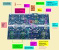
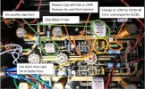
I do not have a proper schematic for this unit. There are a few floating around but cannot be confirmed for my specific version, I believe I have the "Douk Clone" variety. I know that some of the EAR 834p clones do come with a volume pot pre installed. Mine did not.

I like the idea of the inline attenuation but never did consider the impedance aspect. Also I do wonder about the additional rca connections, I don't think the additional RCA connections would greatly effect the sound but if the attenuators are just using resistors internally (or whatever internal components they have) I would assume that installing those same resistors/components directly to the output of the 834p unit might give a slightly cleaner signal?
 
What would, be the cleanest most pure way to reduce the output gain from my EAR 834P Phono stage (clone) from about 50db (seems to be the consensus on the output) to about 40db? So a reduction of about 10db.

I’m fine with adding a high quality volume pot at the output sections but was wondering if using a resistor or some other combination would be a more clean and pure way to reduce the output.


Also I already tried putting in 5751 tubes all three positions as well as various combinations. It did not reduce the gain by more than about a 1/3 of a db in any combination. I tested the output recording test tones and music (12ax7 to 5751). It really didn’t change the volume output in any usable way even with all three positions holding 5751 tubes. It did make it a bit more bright sounding with less bass so I guess there is that.
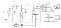
All but the first stage in inside a NFB loop. Thus changing tubes will NOT reduce volume but more reduce quality.
What remains is a resistive reduction on input or output.
A voltage divider at the output is most likely best, 24k + 75k in series with output taken between ground and 24k.
 

Attachments

  • EAR834.jpg
    EAR834.jpg
    54.5 KB · Views: 37
A voltage divider at the output is most likely best, 24k + 75k in series with output taken between ground and 24k.
That represents a significant degradation in output impedance compared to the cathode follower itself.

How are the triode sections configured? Is the input 12AX7 shared across both channels?

Jack
 
All but the first stage in inside a NFB loop. Thus changing tubes will NOT reduce volume but more reduce quality.
What remains is a resistive reduction on input or output.
A voltage divider at the output is most likely best, 24k + 75k in series with output taken between ground and 24k.
Thank you for that. In your opinion would this be a better option than a traditional volume pot regarding impedance?

I’ve used em. Worth a shot.

I might just try them out and see they would be handy to have on hand anyway.
 
The best option - if the first dual triode envelope spans both channels - is to use a lower mu tube type in that position and re-bias it with different resistor values. That's the right way to do this. The entire circuit can be easily simulated in SPICE to confirm overall gain and RIAA accuracy for the change. Anything else, including attenuators with unknown component values inside, will compromise the circuit.

Jack
 
Thank you for that. In your opinion would this be a better option than a traditional volume pot regarding impedance?


I might just try them out and see they would be handy to have on hand anyway.
Fixed resistors or a pot ? A matter of availability of space. In this case trimpots might even be better as they could be individually adjusted (once) and then not more used. Using a pot will risk that you will get a slight imbalance.
 
A 5751 is pretty much a drop-in for a 12ax7 and has a gain of 70 vs 100. Any other tube would need some fiddling to make it work correctly in that spot. Whether or not a 5751 will drop it enough to get the job done I don't know.
 
A 5751 is pretty much a drop-in for a 12ax7 and has a gain of 70 vs 100. Any other tube would need some fiddling to make it work correctly in that spot. Whether or not a 5751 will drop it enough to get the job done I don't know.
That doesn't create much reduction. Even 1/2 the voltage gain is only 6dB. A 12AU7 in that position can provide almost exactly 10dB less, and the non-linearity usually associated with this tube wouldn't be an issue with such small signals. However, anode and cathode resistors would require different values, and likely the 200K B+ dropping resistor as well.

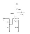
A simpler method would be to replace the 47K cartridge load with a voltage divider. The following values will create 10dB attenuation. Other than completely redesigning the first stage, this is the the least invasive regarding output impedance and RIAA accuracy.

12AX7-Generic.jpg

Jack
 
How about changing the voltage divider between the second AX7 section and the follower? Some folks out on the web remove these components completely but I think it could be changed for a higher attenuation. I don't think the OP explained why a 12dB reduction is needed/desired. I'm also not sure why attenuation on the output with a pot or an inline attenuator is really a problem, assuming it is feeding into a line stage (which we don't know). Line stages tend to have volume controls. Maybe we are trying to get the phono input to a similar level as other inputs? Just wondering as we've speculated a bunch but don't know why and how this unit fits into the system.

Jack's input attenuator is a good option as well and doesn't change the load on the cartridge.

John
 
Have built several versions of these with the different 12xx7 tube variations with the resistor values listed in the diagram(s) above and as long as the B+ voltage is right around 300v they perform extremely well …
 
How about changing the voltage divider between the second AX7 section and the follower? Some folks out on the web remove these components completely but I think it could be changed for a higher attenuation. I don't think the OP explained why a 12dB reduction is needed/desired. I'm also not sure why attenuation on the output with a pot or an inline attenuator is really a problem, assuming it is feeding into a line stage (which we don't know). Line stages tend to have volume controls. Maybe we are trying to get the phono input to a similar level as other inputs? Just wondering as we've speculated a bunch but don't know why and how this unit fits into the system.

Jack's input attenuator is a good option as well and doesn't change the load on the cartridge.

John
That would also work. Change the 330k plate resistor to a pair that adds to 330k and gives the right ratio. 10db is what, 10x? So 33k and 300k with the 33k side to B+.
 
Tampering with anything inside the loop risks degrading the dynamic range and RiAA accuracy. It's not as simple as calculating resistor values.
 
In terms of sound quality, the most benign approach would be an autoformer on the output. The cathode follower output stage should have a low enough output impedance to drive the autoformer.
 
Back
Top Bottom