• The move to the new server is done. There are some software and database maintenance updates in process. This has us passing the hat around to help out. We appreciate any donations. Seriously, even a dollar helps. The payment page may be found here - https://www.audiokarma.org/support.html

Cold solder joints

visiman

Avatar under construction
This older reciever for some reason said to me "Buy me!"

The wife said "Another?" :D

Even though I knew that the Reciever portion and that the amp didn't work it still said "Buy me!" I never had one and was also wondering what it sounded like, But buying an inop piece? But, I did take her home. (actually E-bay) recieved the package today, Very well packed, styrofoam and around the reciever bubble rap, so I can't complain. I have gotten worse. Unpacked it, and took off the cover, Aha! someone has been in here!, but it was the first visitor from looking at the trails. :scratch2: I took a poke around and within a minute found 3 cold solder joints. The first a connector, second a cap (both on the tuner pcb) And a diod that was suspicious. and then a cap on the Main amp board.

"Cool!" I thought. grabbed the soldering iron and wanted to remove the connector and the solder sucked up onto the tip! and left behind a brown ring?

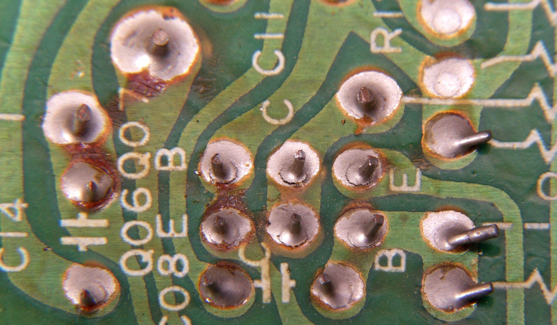
Huh? Where is the pad? Looking closer I noticed that that was the pad. It did not from day 1 take the solder on. And the same with the other CSJs on the board. How did this thing even work for a year? (but knowing that this can happen due to storage and oxidation before the soldering process, or defective/wave soldering sxstems) I just had to check every joint on the card.
The cold solder joints, A blown fuse (that looked ok) And.... To top it off, On the back of the reciever you have to connect the "pre-out" to the "Mains input" via cable. Something that would be quickly overlooked. So the amplifier sections worked the whole time (except for the one small cap)

Three hours up and running! And,... The wife likes it! :smoke:

OK, To the point. After de-soldering with solder wick this is what the pads looked like. This is the first time in my life that I have seen such "FREEZING" cold solder joints. Anyone ever had these before?
 

Attachments

  • Dual1.jpg
    Dual1.jpg
    50.3 KB · Views: 220
  • Dual2.jpg
    Dual2.jpg
    41.8 KB · Views: 212
  • Dual3.jpg
    Dual3.jpg
    48.7 KB · Views: 192
Register to hide this ad
thanks for the pics.

i've seen really bad solder joints before, too.
are those pink spots caused by oxidation?

i guess it doesn't hurt to resolder all the joints when restoring.
 
Those "Pinkish spots" wich I thought was the board at first where the copper pads. This kind of CSJ is still not uncommen in the PCB production. It all depends on the PCB manufactures process (As most PCB's are produced from a different company, and can really ruin a product) Even though this reciever is over 25 years old this still happens today. I am sure everyone has heard of the Re-reflow proces in a normal houshold oven to fix cell phones and play-stations. the only difference is, is that I de-soldered it and the pad was still almost 100% free of any copper/solder activation. This occures today also from bad mixes of solder paste in the SMD process. So, If your 20th century equipment dies! look for things like this. Most PCB's are made in china. Good quality, but also with flaws once in a while.
 
Last edited:
Please excuse the ignorance here, but I haven't taken on mu first recapping yet. What should the card have looked like after the solder was removed? Should it have been darker? What I see there is about the color of a new penny.

Also, did you recognize the cold solder joints with visual inspection of electrical testing? Thanks for any education you provide.

Regards,

D-Ray
 
The early Accuphase stuff is famous for this (with me, anyway). The tinning comes right off the solder pad. To fix, the bare copper must be cleaned with Brasso, and tinned with paste flux and a piece of solder wick with some solder pre-saturated in it. Scrub the copper pad with the wick and a solder iron, and it'll solder up just fine.
 
Just want to clarify something here...

As I get older I tend to stay out of such joints.

But one needs to understand that the term "cold solder joint" is (pardon the pun) loosely applied these days.

Dissolution is key.

When making a solder connection one needs to use care that the eutectic temperature is reached--and that the associated metals being united by such process be at the same temperature as well, so that a proper bond is achieved.

In the old days of point-to-point construction you could almost operate a unit constructed thus without the benefit of soldering a-tall--simply in that there is a good physical connection.

The advent of printed circuitry brought on a much greater dependence on soldering to make a reliable connection.

Hand soldering done carelessly created "cold solder" joints--or what some of my older colleages used to call "rosin joints" in the old days. One learned that there is a certain "sinking in" of the solder that took place once the critical point in temp of all associated materials was reached.

The process of "flow" or "wave" or "induction-process" soldering that came later was a boon to the industry of PC assembly, where the physical connections depend entirely on the solder process.

Solder is not cheap--and never was--no matter it be tin/lead, or any other amalgams of silver, antimony or the like...

The process of "wave soldering" enables the manufacturer in such process to greatly minimize the amount of such expensive material used.

As the fillet radius of each connection gets smaller does it become weakened by its being so. Mechanical vibration is the enemy to a skimpy wave solder job.

In summary the point I am making here is that while a "cold solder" connection is as a result of insufficient heating to achieve adequate dissolution of all associated materials to create the bond, wave soldering always achieves the temperatures required--and successful--i.e. adequate--and thus not cold solder error is achieved, but there is often insufficient solder applied in the process to create sufficient physical strength in the vibrations associated in the daily application of the product.

It is understandable that in manufacture one wants to minimize use of expensive amalgams in assembly, but sometimes the calculations of the amt of stress on some of these solderings are underestimated. On that basis I've made my living over the years.

There was a very good soldering initially--absolutely not a cold solder joint by any stretch. It has always been that there was not enough solder used.

While I have encountered both in my work over the years I prefer to refer to the vast majority of failed solder joints not as "cold" --but rather "fatigued"--as one needs to differentiate as to the cause.

OK; I've said it. Thanks for listening.
 
Last edited:
Areas that always need to be examined in solderings on a PC board are where there are larger components, or where PC boards are suspended in a chassis assembly by components rigidly attached to the chassis--such as power transistors, switches and potentiometers and the like....
 
Fatigued solder:
m509-2.jpg


From amp8.com
 
ke4mcl dude, a dual german made receiver?!?!? lucky dog!

Well They go cheap in Germany, And just for the record the only thing German with this model are the knobs. 100% Japan made! Japan Design, PCB boards, and parts. (I just found that out today) What I also found out that these contact problems on the Synth. board is very common. I like the sound so far, and maybe I'll pick up a few more with the same defekts on e-bay if the price is right.

Hello D-Ray

Usually you cannot remove all of the solder so the surface is silver (tinned)
http://www.n-malek.de/11201/11294.h...mages?q=dual+cr1750&gbv=2&hl=de&safe=off&sa=G
 
Last edited:
Hell - this a Japan made DUAL CR1750... ok... in Germany as I see now not such a rarity

I soldered hundreds of solder joints on two of those. And the Speaker Relais was trouble in one of two.


This older reciever for some reason said to me "Buy me!"

The wife said "Another?" :D

Even though I knew that the Reciever portion and that the amp didn't work it still said "Buy me!" I never had one and was also wondering what it sounded like, But buying an inop piece? But, I did take her home. (actually E-bay) recieved the package today, Very well packed, styrofoam and around the reciever bubble rap, so I can't complain. I have gotten worse. Unpacked it, and took off the cover, Aha! someone has been in here!, but it was the first visitor from looking at the trails. :scratch2: I took a poke around and within a minute found 3 cold solder joints. The first a connector, second a cap (both on the tuner pcb) And a diod that was suspicious. and then a cap on the Main amp board.

"Cool!" I thought. grabbed the soldering iron and wanted to remove the connector and the solder sucked up onto the tip! and left behind a brown ring?

Huh? Where is the pad? Looking closer I noticed that that was the pad. It did not from day 1 take the solder on. And the same with the other CSJs on the board. How did this thing even work for a year? (but knowing that this can happen due to storage and oxidation before the soldering process, or defective/wave soldering sxstems) I just had to check every joint on the card.
The cold solder joints, A blown fuse (that looked ok) And.... To top it off, On the back of the reciever you have to connect the "pre-out" to the "Mains input" via cable. Something that would be quickly overlooked. So the amplifier sections worked the whole time (except for the one small cap)

Three hours up and running! And,... The wife likes it! :smoke:

OK, To the point. After de-soldering with solder wick this is what the pads looked like. This is the first time in my life that I have seen such "FREEZING" cold solder joints. Anyone ever had these before?
 
Back
Top Bottom