
• The move to the new server is done. There are some software and database maintenance updates in process. This has us passing the hat around to help out. We appreciate any donations. Seriously, even a dollar helps. The payment page may be found here - https://www.audiokarma.org/support.html

Combining Filter Caps?

baconbadge

Active Member
Greetings,
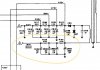
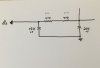
I have a Fisher 500c here where the previous owner combined the three sections of the C92 (50uf, 50uf, 50uf) filter can cap into a single 150uf cap. First pic is schematic, second pic is how it’s rewired:
57B55F61-4E6F-4A57-AAAC-EC92FB095090.jpeg

3C96964D-F882-496B-8D90-454A95B07598.jpeg

The numbers are the same, but does this configuration have any real-world effects on the power supply or downstream where it’s feeding the tuner section? Does putting dropping resistor R136 before or after the filter cap make any difference? And why did Fisher originally use a three-section cap and put R136 between the second & third cap? I’m guessing three caps do a better job reducing ripple than just one, even if the total capacitance is the same.
 
Last edited:
Register to hide this ad
If I had to guess I'd guess the original way may have lower ripple for supply C, as it looks like a CRCRC filter originally vs a CRC filter the way it is depicted in the sketch.
 
ignore please

Shelly_D
The rectifier output goes to the 200uF cap.

I'd agree about the original design having lower ripple, but the original design has just 50 uF at the 160V rail. And this new layout has 3 times that. Perhaps it compensates the ripple by the "brute force". Anyway I'd restore to the original wiring, or wire the new 150 uF between both resistors and add a new 47uF at the output.
 
I suspect that the original had better ripple. A CRC filter composed of R136 and c92A downstream of the resistor and C92B||C92C would likely have less ripple then the modification. In the modified circuit the resistor R136 is serving as a voltage drop, in the original circuit it did double duty as voltage drop and additional filter element.
 
The rectifier output goes to the 200uF cap.

I'd agree about the original design having lower ripple, but the original design has just 50 uF at the 160V rail. And this new layout has 3 times that. Perhaps it compensates the ripple by the "brute force". Anyway I'd restore to the original wiring, or wire the new 150 uF between both resistors and add a new 47uF at the output.
Doesn't the original design have 150uf at the 160v rail too? Or does R136 change the total parallel capacitance based on its location?
 
I suspect that the original had better ripple. A CRC filter composed of R136 and c92A downstream of the resistor and C92B||C92C would likely have less ripple then the modification. In the modified circuit the resistor R136 is serving as a voltage drop, in the original circuit it did double duty as voltage drop and additional filter element.
So it's a low pass filter to get rid of high freq that could affect the tuner?
 
Interesting. I'm always just thinking about 60Hz when it comes to power supplies. I'm assuming these filters are operating in the MHz range? Was there that much high freq garbage on the AC mains back when these were designed? I would think it's a lot worse now.
 
Interesting. I'm always just thinking about 60Hz when it comes to power supplies. I'm assuming these filters are operating in the MHz range? Was there that much high freq garbage on the AC mains back when these were designed? I would think it's a lot worse now.

Ripple occurs at 120 Hz for a full wave rectified signal. Just saying.
 
92B and 92C can be combined into a single cap. The others should not be combined. It will not filter nearly as effectively.

Also just a mention, this leg of the supply does actually work on 60hz ripple. Its effectively a half wave rectifier being fed like it is. The upper group of caps will see 120hz ripple from the full wave voltage doubler.
 
I just saw a video that explains the math behind pi filter networks:
. It's pretty long. At 57:00 is where he calculates the ripple voltage out of the second stage.
 
Hello. I was doing some empiric tests, checking the ripple in a simple power supply feeding a solenoid. Definitely the proper scheme (original circuit, resistor between the 2 capacitors) has much less ripple than combining the capacitors and leaving the resistor on one end.
 
Back
Top Bottom