• The move to the new server is done. There are some software and database maintenance updates in process. This has us passing the hat around to help out. We appreciate any donations. Seriously, even a dollar helps. The payment page may be found here - https://www.audiokarma.org/support.html

Cool article on soldering

dlucy

dlucy67 (Doug)
Staff member
Moderator
Subscriber
Very interesting read

https://motherboard.vice.com/en_us/article/9kggm8/the-art-of-soldering

starts off with:

The technical manual Quality Hand Soldering & Circuit Board Repair sounds like the kind of work that is designed to put you to sleep—especially if you don’t know how to solder.

But if you turn it to the preface, you might be shocked to find one of the most enthralling stories this side of Chesley “Sully” Sullenberger. The 1983 crash landing of a Boeing 767 jet near Gimli, Manitoba, Canada, involved the pilot successfully “gliding” the plane to the ground because it had run out of fuel.

The crash happened for multiple strange reasons, including the fact that the country’s aviation system had recently switched to the metric system and someone forgot to tell the person who put in the fuel.

But the reason why Quality Hand Soldering author H. (Ted) Smith (yes, the “Ted” is in parenthesis) cares? The fuel error wasn’t caught right away, because the fuel gauge was on the fritz. Why was the fuel gauge on the fritz? Bad soldering, of course. It’s a dramatic example in a book about a not-very-dramatic topic.
 
Register to hide this ad
Thanks dlucy. Great article. I remembered about the "Gimli Glider". Why planes crash? show.
 
Good article! I don't know if you've seen this old series by Pace ,9 lessons,all of which are still valid today,and by one of the best voice actors in the business:)

https://www.youtube.com/playlist?list=PL926EC0F1F93C1837
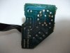
Thanks for posting this @arts I am just starting out and made a boo boo on my circuit board, one of those tiny donuts came off my board due to maybe too much heat. I saw a video on repair board by using a small wire and scraping off a bit of the protection to get at the trace. I am not sure if I can just solder where the spot is (had no continuity) and it may work but it will be worth the try. I wish I had one of those solder sucker and iron in one jobbies! I might have to duplicate the circuit on a PCB prototype and just use that...I do not have any silver adhesive paste yet just ordered from China so it will happily arrive is 10yrs!! LOLSolder Job Switch.JPG
 
Thanks for posting this @arts I am just starting out and made a boo boo on my circuit board, one of those tiny donuts came off my board due to maybe too much heat. I saw a video on repair board by using a small wire and scraping off a bit of the protection to get at the trace. I am not sure if I can just solder where the spot is (had no continuity) and it may work but it will be worth the try. I wish I had one of those solder sucker and iron in one jobbies! I might have to duplicate the circuit on a PCB prototype and just use that...I do not have any silver adhesive paste yet just ordered from China so it will happily arrive is 10yrs!! LOLView attachment 1163263

That happens to many of us. I've always heard it called "lifting a trace". The paths of metal are "traces" and the endpoints where the component lead pokes through and is soldered is the "solder pad". As far as I understand, at least.
 
Last edited:
Thanks for posting this @arts I am just starting out and made a boo boo on my circuit board, one of those tiny donuts came off my board due to maybe too much heat. I saw a video on repair board by using a small wire and scraping off a bit of the protection to get at the trace. I am not sure if I can just solder where the spot is (had no continuity) and it may work but it will be worth the try. I wish I had one of those solder sucker and iron in one jobbies! I might have to duplicate the circuit on a PCB prototype and just use that...I do not have any silver adhesive paste yet just ordered from China so it will happily arrive is 10yrs!! LOLView attachment 1163263

The easiest way to damage a board is too much heat,too much time or too much mechanical force.Or maybe even all three at once,haha. It takes time and practice to get good at this stuff,but even then sometimes things happen,so you can't beat yourself up over it.Find some old boards and learn how to remove and reinstall components while causing as little ''fuss'' as possible.With time you'll learn how to approach different lead situations (lead straight through the hole,kinked over,bent totally flat etc.) and deal with them safely and effectively.Most often, success comes down to experience and intuition.

The all in one desoldering tools are really a godsend,and speed up many jobs,but they aren't the be-all end-all. For many operations,a manual spring-loaded solder sucker may be more effective or even desoldering braid,which I usually use for very tiny or tight work.The more options you have,the easier it gets:)
 
The easiest way to damage a board is too much heat,too much time or too much mechanical force.Or maybe even all three at once,haha. It takes time and practice to get good at this stuff,but even then sometimes things happen,so you can't beat yourself up over it.Find some old boards and learn how to remove and reinstall components while causing as little ''fuss'' as possible.With time you'll learn how to approach different lead situations (lead straight through the hole,kinked over,bent totally flat etc.) and deal with them safely and effectively.Most often, success comes down to experience and intuition.

The all in one desoldering tools are really a godsend,and speed up many jobs,but they aren't the be-all end-all. For many operations,a manual spring-loaded solder sucker may be more effective or even desoldering braid,which I usually use for very tiny or tight work.The more options you have,the easier it gets:)
Right you are. I do have old boards and I knew I should have but I did not expect the unexpected!! Ha ha! I do the the braided stuff and using a 60W pen with a good solder sucker and it worked great I just started using the pen tip to try to open the solder hole a bit more and sure enough...too much time on it and it lifted it out! LOL

Well darn it, I will try and make the same circuit and see what happens.

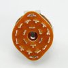
I ordered the 3P4T rotary switch but the picture is showing 4 pins on the bottom with the other 12 so 16 pin

s-l1600.jpg

and mine is a 15 pin!

16 pin.jpg

I hope the guys reference pic is wrong, the cost was $1.30 but the shipping was $12! LOL

I wonder if I can wire that switch where: Off/A/B/A+B will work? Because the positioning is different from the two kinds but again the one I ordered should show just three pins nearing the center!

Nice to meet you take care bud!
 
The correct soldering iron is crucial for producing quality connections. The correct size, temperature and amount of heat are all very important along with good technique.

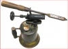
Below is my go to soldering iron for delicate work (and not so delicate work). The variable temperature comes in handy.

upload_2018-4-15_0-25-3.png

And for field work it is portable.
 
That happens to many of us. I've always heard it called "lifting a trace".
Guys I forgot to ask, can I take a 'signal trace' from another board and replace it?? I did see a video where the guy scratches and exposes the board and solders in a small trace but I am still hoping to solder in the part and some of that solder takes to the circuit. But, if not, I will rebuild the circuit on a PCB board and hope for the best!! Have a great night!

@I LIKE MUSIC how many BTU's to watt ratio is that puppy! LOL
 
Guys I forgot to ask, can I take a 'signal trace' from another board and replace it?? I did see a video where the guy scratches and exposes the board and solders in a small trace but I am still hoping to solder in the part and some of that solder takes to the circuit.
If you've had a trace lift the repair is generally straightforward: with a dental pick or other sharp object, scrape the enamel coating off the remaining trace to expose enough bare copper to solder to, then solder in a short length of copper wire -- or use the wire leg of the replacement component -- to replace the lifted trace.
 
If you've had a trace lift the repair is generally straightforward: with a dental pick or other sharp object, scrape the enamel coating off the remaining trace to expose enough bare copper to solder to, then solder in a short length of copper wire -- or use the wire leg of the replacement component -- to replace the lifted trace.
I will do both, I will try the scratch method and add some wire, if no go then I will rebuild circuit on a piece of PCB.
 
Neat article, thanks!
I did production PCB QC/repair for nearly a decade. Cold solder joints were the bane of my existence back then.
That and tantalum caps installed backwards - I can still recognize that smell from a block away!
Lifted traces were very rare with our fairly conscientious PCB assemblers.
Fortunately, the bosses early experiments with a very old & tired wave solder machine were mostly toasted and tossed - but he did eventually get it working reasonably well. Another smell I can live without having to experience ever again!
 
Thanks for the links. :thumbsup:

I watched the Pace videos and saw something he's doing that I'm not. He's cutting the lead before soldering and making sure that he covers the cut part with solder. I've been cutting my leads after soldering and not covering the cut part with solder. Is my method completely wrong?

Flux recommendations.
 
Last edited:
I have to agree with Arts. Too much heat, too much time, lack of flux, are all recipes for disaster. But there's caveats. I use 700 degree tips and most people would gasp, but the idea is to get in and out as quickly as possible. I can pull a 1206 package off in less than half a second. If you're spending any more than a second on any joint, you're risking it, including thru hole.

Another common mistake is applying solder to the tip. Heat the joint, apply solder to the joint sparingly. And for removal, if you're not concerned about the component you're removing, destroy it. I've seen people spend waaaay more time than they should trying to remove a thru hole component. Clip those leads at the body of the part, heat and with tweezers pull each lead out. Then clean up afterwards. No more lifted pads :) Remember, flux is cheap!

ISO9000 certified milspec rework specialist.
 
Thanks for the links. :thumbsup:

I watched the Pace videos and saw something he's doing that I'm not. He's cutting the lead before soldering and making sure that he covers the cut part with solder. I've been cutting my leads after soldering and not covering the cut part with solder. Is my method completely wrong?

In most production environments, one of the earlier steps is called prep. Component leads are pre-bent and trimmed in fixtures and sorted for easier hand loading. For example, tantalum caps will crack at the base if shoved into a board down to their base, so the leads are pre-formed so they they float above the PCB surface to reduce stress. Automated thru hole placement is the same way as leads are trimmed during placement. If components still had full length leads during install, they wouldn't clear during wave solder. He likely just pretrimmed for the video and honestly makes no difference.
 
Back
Top Bottom