• The move to the new server is done. There are some software and database maintenance updates in process. This has us passing the hat around to help out. We appreciate any donations. Seriously, even a dollar helps. The payment page may be found here - https://www.audiokarma.org/support.html

CR-1000 humming from both channels

TR802 was replaced 2 months ago to tackle the popping/crackling and it was a success.
TR802 has not been replaced since the humming/+B=62V? started. Since TR801 was just replaced makes TR802 suspect faulty.
It should be replaced.

To me the strangest thing is that my both CR-1000s worked great until I started to mess with Filter Amp board and Tone Amp. The problems appeared the moment I switched on the amps after resoldering some wires there and replacing the small caps. Coincidence?
Ignore nothing, things happen for a reason. Coincidence? Very rarely happens in hifi.
We have to work on symptoms and try and build up facts. There appears to be multiple problems, ie, the 62V supply and the humming.
The 62V supply is just WRONG. Being part of the power supply it should be fixed first. There is an outside chance that it's causing/contributing
to the humming but I think that's unlikely. There are plenty of causes for humming including grounding issues and caps. One step at a time.
I've had a long lasting grounding problem on a CA-1000 in the area of filter and tone boards, so I wouldn't dismiss work in this area as a cause.

Can this formula be used? The results were sensible that gives me hope
Certainly. Power=I^2 x R, the formula can be used.

All resistors but 1 gave results just shy of 0.5W. One gave around 1.6W so 1.5W would be alright.
In such cases the normal procedure is to go to the next highest rating, ie 2W, however as they are fusiable I'd be comfortable with the 1.5W
 
Regarding the humming, you can try some resistance measurements.
Outside chance it will show something.

With CR powered off/unplugged. RED probe of multimeter connected
to chassis, eg, phono ground or black speaker post. With BLACK probe
of multimeter measure the resistance at,
- Volume board, BROWN outer wrap, middle wire, probably black
- Power amp board, Black E wire, L&R side

You can test any EARTH point of the CR in the same way. Ideally
expect zero ohms however it may be 1 or so. The layout is a little
different to the CA-1000 so I can't help much.
 
The +/-50V supply for the preamp and front end of the power amp
is running at about +/-62Vdc. The +33V is at about +40Vdc.
This will be putting aditional strain on some components
- C609 220uf/35V, both power amps
- Power amp bias is probably totally out of whack
- C481,2 10/25V, Tone control

Please check the bias (TP3 & 4) and the voltage across TP1 & 2
as per the service manual "MAIN AMPLIFIER ADJUSTMENT" page 30.
You can check the mid-point also but it's unlikely to be an issue.
With the extra voltage, VR602 & VR603 may need to be wound back a
little. Check both power amps. If TP1&2 voltage is less than 16V
then I wouldn't bother. Likewise if TP3&4 is less than 100mV.
The idea is to make sure the overvoltage is not causing problem
on the power amp.
 
Yeah, I will check all this when back home.
Meanwhile I think I noticed mistake in schematics about Tone Amp PCB. The position of 2 brown wires and one white is switched around.
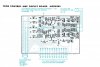
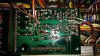
tonecontrol.jpg tone_resized.jpg
 
  • Like
Reactions: mbz
Yep, the photo shows that the white wire in the orange wrap and the
2 brown wires don't match the screen print/board layout above. However
the photo looks correct.

The brown wires are +50V supply, C499, R485, 6 are on the same track
which matches the schematic. Also, the white wire is after R493 and
C485 which also matches the schematic.

The wiring is correct, error in screen print/board layout above.

Good observation.
 
So in my humming CR-1000 I replaced TR802 with another TIP31C and voltages have come back to norm, humming is gone.
In my dead CR-1000 I did the same + replaced the dead fusible resistor FR803 and the unit powers on, though the right channel is still missing.
I tested the removed TIP31Cs, they got shorted big time. They are different brands, Fairchild and STMicro.
So the TIP31C can't hack the temperature for more than 2 months? It's the hottest element in the whole receiver, around 80C. Or maybe I shouldn't have replaced TR801s with KSC2383? Now I soldered back SC1213A in one of the units.

About the missing right channel.
I have no voltage on the red wire on the right in the picture above of the Tone Amp board. It goes to volume pot. I have 8mV on the white (left channel?). I have around 8mV on both red and white on the left side of the board, they go to loudness board.
There's also zero on the red wire going from loudness board to volume pot. But the red wire coming from Tone board to loudness board is live :/
 
Last edited:
So in my humming CR-1000 I replaced TR802 with another TIP31C and voltages have come back to norm, humming is gone.
OK, that's good but the concern is why did it blow. The TIP31C appears to be a good substitue, it has better spec's than the 2SC1061 expect for peak collector
current 5A v 8A. I would put a heat sink on the TR if it does not have one, prefer to use those insulation tabs as the case is live (=collector). TR802 is blowing
because of some problems down stream. Maybe take a look for any heat stress signs on the pcb in the tone/filter boards and the tuner section. Not much
help I'm sorry.

About the missing right channel.
The left and right channel wires carry audio signal. Ok for some background noise, however 8mV sounds high.

There's also zero on the red wire going from loudness board to volume pot. But the red wire coming from Tone board to loudness board is live :/
Expect this is the red/white pair in the orange wrap. What do you mean by live? how many V/mV
 
OK, that's good but the concern is why did it blow. The TIP31C appears to be a good substitue, it has better spec's than the 2SC1061 expect for peak collector
current 5A v 8A. I would put a heat sink on the TR if it does not have one, prefer to use those insulation tabs as the case is live (=collector). TR802 is blowing
because of some problems down stream. Maybe take a look for any heat stress signs on the pcb in the tone/filter boards and the tuner section. Not much
help I'm sorry.


The left and right channel wires carry audio signal. Ok for some background noise, however 8mV sounds high.


Expect this is the red/white pair in the orange wrap. What do you mean by live? how many V/mV
Has C486 (polar tantalum) been replaced? Replace with Nichicon KL
I replaced now on both sides with electrolytic. I have 80mV in the red wire now, in neutral and white still 8mV, maybe coincidence.
I checked the other CR-1000, over there I have 14mV in all wires, red, white and neutral, on both sides of pcb.
 
Last edited:
OK, that's good but the concern is why did it blow. The TIP31C appears to be a good substitue, it has better spec's than the 2SC1061 expect for peak collector
current 5A v 8A. I would put a heat sink on the TR if it does not have one, prefer to use those insulation tabs as the case is live (=collector). TR802 is blowing
because of some problems down stream. Maybe take a look for any heat stress signs on the pcb in the tone/filter boards and the tuner section. Not much
help I'm sorry.


The left and right channel wires carry audio signal. Ok for some background noise, however 8mV sounds high.


Expect this is the red/white pair in the orange wrap. What do you mean by live? how many V/mV
Yeah, orange wrap, 8mV in all 3 wires going to loudness board.
 
I thought there were a few volts in the wire, so the guess to replace the capacitor. These voltages won't
cause your dead right channel, they will cause background hum/hiss. Suggest you check solder connections
generally everywhere, yep, it's a PITA, but they do cause problems. Initially check the solder connections of
these wires on the tone and volume/loudness boards.

I need to recap. You have a CR that has no sound out of the right channel. Left is ok, please correct me if wrong.

Have you done the basics?
Deoxit switches/controls
Faderlube POTS,coupler switch
Used the amp as a separate, first as a PRE, then a POWER amp to isolate the problem.
Same problem with speaker A, B,,,
Same problem through headphones?
Same for other inputs TUNER/PHONO/AUX

The protection circuitry has not picked up a problem so the cause will probably be due to bad contact/connection.
 
I thought there were a few volts in the wire, so the guess to replace the capacitor. These voltages won't
cause your dead right channel, they will cause background hum/hiss. Suggest you check solder connections
generally everywhere, yep, it's a PITA, but they do cause problems. Initially check the solder connections of
these wires on the tone and volume/loudness boards.

I need to recap. You have a CR that has no sound out of the right channel. Left is ok, please correct me if wrong.

Have you done the basics?
Deoxit switches/controls
Faderlube POTS,coupler switch
Used the amp as a separate, first as a PRE, then a POWER amp to isolate the problem.
Same problem with speaker A, B,,,
Same problem through headphones?
Same for other inputs TUNER/PHONO/AUX

The protection circuitry has not picked up a problem so the cause will probably be due to bad contact/connection.
The problem is on preamplifier on all sources, headphones and speakers. All pots and switches clean.
 
The RED wire is for the right channel and 80mV is too much a coincidence for me.
The CR uses 2SC1345 transistors through out. The general opinion (polled 2 people) is
that these can go noisy and eventually fail. The preferred replacement is KSC1845FTA.
If you have some handy you could replace TR471->476 on the tone board. They are
also in the phono stage and the filter amp so maybe get 20, they are cheap.

I don't think these TR's are the cause of the dead channel, I would be expecting higher than 80mV.

This voltage may be coming from "anywhere", being passed back from the filter board.
On the TONE board, do you have any posts, probably with wire wrap, hopefully they are numbered.
With the red probe on pin 12, black probe on pin 14, can you measure the dc voltage xxmV.
I want to measure the voltage drop across R500 and the end that has the highest voltage to
point to the next component.

As an outside chance, you could try playing music through the amp, black probe on chassis,
and measure dcmV at each of the red and white wires on the tone/volume/loudness boards.
The idea being to "trace" the music through the various stages of the amp. No need to record
the voltages. At each point compare red and white wires, if they are the same then move on.
May need to set MM to AC volts, depends how cheap you MM is. Again, this is an outside chance.
 
The RED wire is for the right channel and 80mV is too much a coincidence for me.
The CR uses 2SC1345 transistors through out. The general opinion (polled 2 people) is
that these can go noisy and eventually fail. The preferred replacement is KSC1845FTA.
If you have some handy you could replace TR471->476 on the tone board. They are
also in the phono stage and the filter amp so maybe get 20, they are cheap.

I don't think these TR's are the cause of the dead channel, I would be expecting higher than 80mV.

This voltage may be coming from "anywhere", being passed back from the filter board.
On the TONE board, do you have any posts, probably with wire wrap, hopefully they are numbered.
With the red probe on pin 12, black probe on pin 14, can you measure the dc voltage xxmV.
I want to measure the voltage drop across R500 and the end that has the highest voltage to
point to the next component.

As an outside chance, you could try playing music through the amp, black probe on chassis,
and measure dcmV at each of the red and white wires on the tone/volume/loudness boards.
The idea being to "trace" the music through the various stages of the amp. No need to record
the voltages. At each point compare red and white wires, if they are the same then move on.
May need to set MM to AC volts, depends how cheap you MM is. Again, this is an outside chance.
I have plenty of those replacement transistors.
I don't understand where those pins 12 and 14 you are referring to are.
 
Last edited:
transistors replaced. voltage in red wire has gone up even more, to 117mV. No right channel still.
 
Last edited:
I don't understand where those pins 12 and 14 you are referring to are.
OK, this is going to be slow. You need to follow the logic and refer to the schematic. Depending on one set of results you need to guess
where to take the next measurement. Probe orientation (red/black) is important as is the voltage positive or negative.

The guess is that the high (100mV) in the right channel is connected to the right channel being down, confirmed as a preamp issue.
The process is to track down the source of this 100mV, moving in the direction where the voltage increases. The starting point is R500
on the tone board.

You have measured the +100mV (or so) on the red wire in the orange wrap on the tone board. This is the node/junction between R500
and R494. The next step is to work out which end of R500 has the higher voltage.

Red probe on red wire in orange wrap, black probe on jumper J474 or pin Bc on tone or volume boards, see pic.

Capture44.JPG

If the voltage is positive then node R500/R494 is higher. Next step is R494 and R496 with black probe on chassis.
This is probably a grounding issue.

If the voltage is negative then pin Bc is higher, next measure at the red wire in the yellow wrap on either the loudness
or filter boards, black probe on chassis.

This is probably 20 minutes work with an oscilliscope, so if you know someone...
 
OK, this is going to be slow. You need to follow the logic and refer to the schematic. Depending on one set of results you need to guess
where to take the next measurement. Probe orientation (red/black) is important as is the voltage positive or negative.

The guess is that the high (100mV) in the right channel is connected to the right channel being down, confirmed as a preamp issue.
The process is to track down the source of this 100mV, moving in the direction where the voltage increases. The starting point is R500
on the tone board.

You have measured the +100mV (or so) on the red wire in the orange wrap on the tone board. This is the node/junction between R500
and R494. The next step is to work out which end of R500 has the higher voltage.

Red probe on red wire in orange wrap, black probe on jumper J474 or pin Bc on tone or volume boards, see pic.

View attachment 898872

If the voltage is positive then node R500/R494 is higher. Next step is R494 and R496 with black probe on chassis.
This is probably a grounding issue.

If the voltage is negative then pin Bc is higher, next measure at the red wire in the yellow wrap on either the loudness
or filter boards, black probe on chassis.

This is probably 20 minutes work with an oscilliscope, so if you know someone...
Actually the higher voltage in red wire that is channel right is in the brown wrapper on the right side of the pcb going to volume pot. The wires in orange wrap that go to loudness are ok.
So I thought it was something on the pcb between those 2 bunches of wires.
 
Last edited:
Actually the higher voltage in red wire that is channel right is in the brown wrapper on the right side of the pcb going to volume pot
I don't see this taking out the right channel...

Measure dc voltage, red probe, black? wire(earth) brown wrap on tone board, black probe on chassis, expect 0mV +/-
Measure dc voltage, red probe, red wire, white wrap (in red wrap?) on loudness board, "ri", black probe chassis. Which
is higher voltage (red wire on loudness or tone board)
 
With CR powered off/unplugged, put black probe in AUX1-Left RCA, red probe at white wire, brown wrap tone board. Input selector
set to AUX-1, measure resistance.

Repeat for AUX1-Right RCA and red wire brown wrap.

The resistances should be about the same +/-20%
 
With CR powered off/unplugged, put black probe in AUX1-Left RCA, red probe at white wire, brown wrap tone board. Input selector
set to AUX-1, measure resistance.

Repeat for AUX1-Right RCA and red wire brown wrap.

The resistances should be about the same +/-20%

This measurement should confirm that the switches are clean.
 
Back
Top Bottom