• The move to the new server is done. There are some software and database maintenance updates in process. This has us passing the hat around to help out. We appreciate any donations. Seriously, even a dollar helps. The payment page may be found here - https://www.audiokarma.org/support.html

CR-2020, Main Circuit Board reading: Meaningless or a clue?

hertzdonut

Press Play and Stand Back
Brief background on this CR-2020: With the help of this forum, I got this beautiful unit up and running about 5 years ago. All good. The last couple of years, due to moving and life in general, it got very little use.

Recently, I started using it again as part of bedroom setup. I noticed switching through various Modes (Stereo, L, R, etc) would result in improper playback, meaning, I would get playback L & R even if Mode was set to L, switching Mode to Stereo makes the R signal go weak, etc.

I suspected a dirty Mode switch as well as Volume and Balance knobs and decided to finally take a plunge and open it up. Once the case was off, I pulled that upper Tuner Circuit Board and moved it a bit so that I could get better access to Deox'ing the switches and knobs. Over a period of 5 days, I sprayed DeOxit multiple times into the weep holes, and worked the switches and knobs hundreds of times.

Decided to fire it back up, no change. Well...heck.

Time for more work...(First a note about work I completed from 5 years ago: All Service Bulletin work completed, new outputs on the right channel, replaced a couple caps on the Power Supply Boards and the Electrolytic Cap Circuit Board. Replaced the Cap Coupler thingy. After that, like I said, all good.)

FF to this week: In addition to DeOx'ing the switches and knobs, I also removed the Cap Coupler from the back of the unit so that I could DeOxit that. Worked that switch a hundred times. With those massive heatsinks pulled, I removed the Main Circuit boards and replaced the 458 transistors on each board. Triple-checked my outputs (removed from circuit) using the six-way diode test. All good. Lastly, gave little tweaks to the Idle Current with the trimmers, left is reading 10.2, right reads 10.3. Near perfect.

Despite all the above, it hasn't made any change.

Which brings me back to my Post title...I don't know what readings I should get nor even where to take them, but decided to run through O, E, B+ and B- on the Main Circuit Boards and compare the L and R channels. My thought was each lug should be comparatively the same. I fire up the unit, grabbed my multimeter, and put ground to chassis.

Turns out, I got one reading different between the two. Here's all, from left to right, as if you are viewing the board from the component side:

CHANNELOEB+B-
LEFT+7 mV-.2 mV+58.8 mV-59 mV
RIGHT-2.7 mV-.2 mV+58.9 mV-59 mV

Is that reading of -2.7 mV meaningless, or an indicator there's an issue somewhere?

Thanks,

Jeff
 
Register to hide this ad
You have nothing to worry about there.

Often times, worse values will be present on the outputs of a brand new amplifier.

Distance from 0 is what you're looking for. under 10mV neg or pos is miniscule here.

You did the right thing in performing the factory service bulletins.
 
Thanks for your insights, gentlemen!

Good news and bad news, I guess. Good in that either reading on the ( O ) output isn’t terrible (+7mV on the L channel notwithstanding!*) or causing my Mode switch issue.

Bad in that I have a Mode switch issue, or at least that’s the symptom. Logic might dictate that the switch, despite my best Deoxit efforts, is still bad.

So, I’m left with two choices: Tear into it further, attempt a dismantle of the switch itself…or live with the way it is.

If there’s a third option, I’m all ears.

Neither way seems especially appealing, but I’m not going to decide tonight.

Again, thank you zenith2134 and Avionic.

Jeff
 
The switch consists of 2 tracks which run most (3/4?) the length of the switch. 4 sliding contacts run on the tracks, the contacts are housed in a plastic hood/holder. This holder is a barrier to any deoxit sprayed from above through holes etc. If the far end of the switch is open, you might get some deoxit into the slider/contact area if you spray into the end parallel to the circuit board, pix below.

This is only a work around, may give temporary "relief". Switch needs to be desoldered from board and cleaned. Unsure if throwing it into an ultrasonic cleaner would do the job or damage the switch or..., need to evaluate. I disassemble the switch and clean, yeah PITA. Bad news is that other such switches probably need a clean. Expect some improvement to SQ.
 

Attachments

  • SlideSwitch.png
    SlideSwitch.png
    611.3 KB · Views: 9
It's funny, mbz, you mention spraying into the far end of the switch. I did that a fair amount, but assumed it was a waste of time, figuring that was the wrong spot to spray!

Man, I don't look forward to tearing into that switch. There's a saying in the construction industry, you might have heard before: The four most expensive words when remodeling are "While you're at it..." I would offer up an "electrical corollary", if I may: The four most time-consuming words when working on gear are "You've come this far..."

After work today, I'm going to take another look at it, the switch, what's involved to get it removed and so on. Psych myself up. Maybe I will tackle this.

And thanks, mbz, for the information and diagram!

Jeff
 
Sure...After dis-assembly...
Have you confirmed dis-assembly is necessary?

I plan the following on switches from a parts unit.
disassembly
pix before
reassembly
toss entire switch in US cleaner
disassembly
pix after

problem is that any grit dislodged is mostly trapped in the plastic holder.
Unsure of the effects of US on the plastic holder, possibly weld it to the switch??
 
Have you confirmed dis-assembly is necessary?

I plan the following on switches from a parts unit.
disassembly
pix before
reassembly
toss entire switch in US cleaner
disassembly
pix after

problem is that any grit dislodged is mostly trapped in the plastic holder.
Unsure of the effects of US on the plastic holder, possibly weld it to the switch??
If your using heat .. I don't know about that old plastic ( slider pocket) piece.. My ultrasonic only has one heat setting " real hot " .:biggrin: I dis-assemble so I can physically inspect components. The plastic pieces get the room temp water.

What are you using for cleaning solution ? I'm using a 3 : 1 solution of distilled water & Simple Green " Crystal ".
 
Last edited:
All the lubricant will likely get removed from the internal mechanical pieces and deposited on the electrical pieces. And will need to be relubed. Slider switches will need to be partially dis-assembled enough to accomplish that task. Old lube really loads down the cleaning solution.
 
Last edited:
  • Like
Reactions: mbz
All the lubricant will likely get removed from the internal mechanical pieces and deposited on the electrical pieces. And will need to be relubed. Slider switches will need to be partially dis-assembled enough to accomplish that task. Old lube really loads down the cleaning solution.
Have you confirmed dis-assembly is necessary?

I plan the following on switches from a parts unit.
disassembly
pix before
reassembly
toss entire switch in US cleaner
disassembly
pix after

problem is that any grit dislodged is mostly trapped in the plastic holder.
Unsure of the effects of US on the plastic holder, possibly weld it to the switch??

All lubricants and grime "might" get dissolved but not guaranteed. Best to disassemble before throwing in the cleaner.

Besides, new lubricants will likely need to be re-applied, hence having the thing open is almost mandatory for proper lube, read controlled lube.
 
  • Like
Reactions: mbz
Have you carefully inspected all the solder joints for this switch on the back side of the PCB? Before removing the switch, a reflow on all the connections might not be a waste of time. Or, it might be but there’s one way to find out.
 
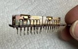
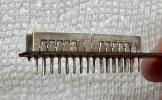
Took a while, but I was able to remove the switch and carefully open it up. Sure, there’s carbon build-up, but to my eyes, I’m seeing shiny metal along the sliding contact points. No worries though, I intend to clean away all the carbon.

Jeff

IMG_1305.jpegIMG_1304.jpeg
 
Once you have one under your belt.. The rest are a piece of cake.
 
I didn’t have any Simple Green, but I do have Krud Kutter. Used that with a soft toothbrush, then a wet polish with 2000 grit. Spray rinsed with distilled water. I don’t know if that will cure my original problem, but at least this switch is clean.

I was planning on lubing with DeOxit Gold G5.

Jeff

IMG_1308.jpeg
 
Unfortunately, the newly cleaned and lubed switch did not solve my problem. I decided to put it all back together, enough for testing, and my symptoms remain exactly the same. There's something else going on. What, I haven't a clue.

But I do have one question. Can outputs be "weak" even though they pass the six-way diode test? The appropriate pins conducted at approximately .55, which I understand is in the acceptable range between .45 to .65. However, my right channel is pretty weak (as it was before I did all the work noted above) and that channel still has the 554 and 424 outputs (probably original?).

Yeah, I am clutching at straws here.

Jeff
 
I had a kenwood KA-7002 that had the same issue, a weak channel and the mode switching was all wacky. It turned out to be extremely high ESR's on a couple capacitors on the tone board.

I read you only replaced some power supply caps. I think it's time for a total re cap. Shotgunning is not always advised but these are over 40 years old and most caps are probably at EOL or getting close to it.

But check the caps on the tone board first. value might be ok but you need to check ESR. Those cheap little parts testers work great for things like this and testing transistors .

Athanasios
 
Athanasios, thanks for sharing that! Now I'm curious to do some more checking. That tone board is a pain in the butt to access. Ah well. Tomorrow is another day. I'll take a breather as my ESR checker won't be here until Monday anyway.

Thanks again!

Jeff
 
Back
Top Bottom