• The move to the new server is done. There are some software and database maintenance updates in process. This has us passing the hat around to help out. We appreciate any donations. Seriously, even a dollar helps. The payment page may be found here - https://www.audiokarma.org/support.html

CR-3020 Amp board problems

kcvintage

Active Member
I have a nonworking CR-3020 amplifier board. I'm checking each board with +- rail voltage on (b) and no output transistors installed. Each of the driver transistor collector voltages (at TR609, 610, 616 and 617) reads approx. +- 10.0 V. Other transistor voltages read correct. Each driver transistor tests good on a Peak DCA75 tester. Why are all four driver collectors showing higher voltage than they should? Looking for suggestions to solve the problem. TIA!
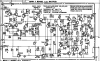
cr3020.pdf 2023-04-29 10-21-55.png
 
Register to hide this ad
Little unclear, I'd expect TR609c at +1.2Vdc and TR616c at +B
Measure +/-B TR616b, TR609e and voltage at the SP (speaker) pin.
Check resistance of all fusibles, these have a bad habbit of drifting high
(after being stressed)
 
I'm checking each board with +- rail voltage on (b) and no output transistors installed.
+/- b or +/-B.. Your probably measuring the +/- B rails +/- 72 vdc. Which are much higher than +/- b..
 
Last edited:
Little unclear, I'd expect TR609c at +1.2Vdc and TR616c at +B
Measure +/-B TR616b, TR609e and voltage at the SP (speaker) pin.
Check resistance of all fusibles, these have a bad habbit of drifting high
(after being stressed)

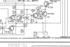
Attempting to compare actual voltages to schematic voltages - I measure minus -8.74V at TR609c, vs. 1.83V as per schematic.
TR609e is 72.4V so very close to schematic. No voltages at speaker pins. All fusibles measure per schematic.
Thanks!!
 
I did check FR604 and I installed a 10 ohm same wattage replacement for the fusible. Looks like I should have used 100 ohms. Will replace and post results tomorrow. Thanks!
 
TR610e is around -72.8V. All of the base and emitter voltages for each of the 4 drivers are near schematic spec, but all four of the collector voltages are significantly high.
 
What voltage are you seeing at the output transistor collector sockets ? ( one of the threaded screw holes. )
 
Approx. -10.0V at each of the output collector terminals.

As expected, correcting the R604 resistor value from 10 ohms to 100 ohms made no difference for this problem. I did learn to check part values and not assume Mouser always bags accurately. Bag says 100 ohms but they sent 10 ohms and I just assumed and installed...

Could the JFET be bad? Never dealt with one before.
 
Voltages are correct leaving the power supply, but low in places and high in places at the drivers and at the output sockets, depending on Vc, b or e. All of the drivers test good. Never seen this before. Thanks for your help!.
 
Voltages are correct leaving the power supply,
The +/- B is the unregulated supply. Should be a straight wire from the big filter caps to the output transistors collectors.

What DC voltage are you seeing right at the two big capacitor solder lugs ?
 
No voltage to the filter caps. AC 107V to the full wave diode bridge. From the block diagram it looks as though voltage goes to the protection relay on the "Protection Circuit Board" (top right below) before going to the diode bridge and on to the filter cap circuit board - I think. Transformer voltages are good. The two fuses for the protection relay are good - someone had 10A fuses installed, should be 12A. There are two diodes on the Protection Circuit Board so I am wondering if they are fried. yamaha-cr3020-receiver-schematic.pdf 2023-04-30 16-25-18.png hfe_yamaha_cr-3020_service_en.pdf (SECURED) 2023-04-30 16-21-49.png
 
Thanks! I'll troubleshoot it. I have voltages from the transformer to the fuses, but no voltages at the bridge rectifier. So maybe the relay is open due to a problem in the circuit above.
 
Back
Top Bottom