• The move to the new server is done. There are some software and database maintenance updates in process. This has us passing the hat around to help out. We appreciate any donations. Seriously, even a dollar helps. The payment page may be found here - https://www.audiokarma.org/support.html

Crazy High 15v DC Offset!

Yes (I presume that's AC audio voltages you're reporting). Looks like you're on the right track.

WIth four identical sections you should be able to measure voltages and compare. Piece 'o cake - right?

Me, I'd zero in on C27 or C58, both electrolytic coupling caps. Second suspect would be the input FET. However best to take this systematically - use your scope to probe the base and collector of each transistor (or the gate and drain of the FET) and see if/where you're losing the signal.... then compare DC quiescent voltages with the other channels.
 
Yes (I presume that's AC audio voltages you're reporting). Looks like you're on the right track.

WIth four identical sections you should be able to measure voltages and compare. Piece 'o cake - right?

Me, I'd zero in on C27 or C58, both electrolytic coupling caps. Second suspect would be the input FET. However best to take this systematically - use your scope to probe the base and collector of each transistor (or the gate and drain of the FET) and see if/where you're losing the signal.... then compare DC quiescent voltages with the other channels.

Yep, AC audio voltages. That board has new electrolytics and the 2sc1312's replaced with KSC1845's, and the 2sa725's replaced with KSA992's. I'll pull it out tomorrow and check my work, but I think I remember that rear channel being weak before I did any work. It's hard to recall what all was wrong as it had so many issues all over the place. Either way it shouldn't be too bad to pull it out.

I am hoping it's not the FET, those are practically unobtanium from my understanding. It's a 2sk30 if anyone happens to know a sub. It may be easiest to find a parts board on the auction site and see if one can be pulled from there if that ends up being the culprit.

Edit: It looks like peace.love.and.music has both the Y and GR versions of the k30 available! Will report back tomorrow with results.
 
Last edited:
New components aren't necessarily good components... and you could have made an error in replacing a component. I've been there and done both.

A 2SK30 crosses to a NTE459. This isn't a critical component, most any N-channel low noise FET should work fine here. However, I see some on eBay from a fellow AK member so you shouldn't have an issue finding 'em if you need to.
 
Compare the AC signal at the collector of Q7 and Q6. If they are about the same your FET is good. If not, check the DC voltage on the "west" side of R79 and R35. Compare with another channel. If one of the supply filter cap (C7, C55) is backward the supply voltage might be low.
 
Compare the AC signal at the collector of Q7 and Q6. If they are about the same your FET is good. If not, check the DC voltage on the "west" side of R79 and R35. Compare with another channel. If one of the supply filter cap (C7, C55) is backward the supply voltage might be low.
Q7 collector = 0.098VAC / 11.88VDC
Q6 collector = 0.091VAC / 11.09VDC

R35 = 5.0 VDC
R79 = 28.5 VDC

C7, C25, C55, and C58 are all oriented correctly with correct values.


After taking those measurements I was probing around and saw some funny stuff around Q11. Took another closer look at the board markings and sure enough it was installed incorrectly. I'll grab a fresh one from the pile after lunch and see what happens!
 
I don't see how you can have more than 11VDC at the collector of Q7 and Q6 with only 5VDC of supply. But at least your voltages show that the first stage is good.
 
Changing Q11 fixed the weak channel issue. As for where that 11VDC is coming from? I have no idea where it's coming from I checked and it's still there. This receiver is far beyond my knowledge I am doing the best I can to follow along and try to think through things myself and hopefully learn something new in the process. That weak channel seems to have been "fixed" - for now.

The only issue left to troubleshoot had to do with the CD-4 subchannel assembly. On this receiver CD-4 can only be decoded from the phono inputs. If FM, AM, AUX are used with the mode switch set to CD-4 then it is simply defaults to four channel stereo instead of a matrixed quad.

The issue here is when the mode switch set to CD-4 all speakers play normally (in 4-channel stereo) except when the input is changed to phono 1 or 2. Since all other quad modes are working as they should on all inputs I don't think there is an issue with the decoder / matrix boards, but there is a lot here that I don't understand. To me, it seems as though there is likely another broken wire somewhere in it's sheath.

If I understand correctly the CD-4 board only receives a two channel signal and 30kHz carrier where it independently decodes the rear channels. That would mean that my issue with the rear right channel is either on this board or somewhere after it?
 
The CD-4 issue appears to have "fixed" it's self. I am assuming that my assumption there is an intermittent short somewhere is correct. I don't have any CD-4 albums or the correct cartridge anyways. For whatever it's work the little red light does turn on when pin 19 is brought to 0V with a jumper to defeat the muting circuit. Maybe one day I'll get into CD-4.

SQ is working how it should and sounds great. I'm going to go through and check out the bias & offset adjustments one more time and call this receiver done.
 
Outstanding! You have much more fortitude than I, tackling that thing. I'm not a fan of working on Asian equipment due to the afore-mentioned documentation clarity, usually substandard PC boards whose traces lift if you look at 'em crosswise, and a forest of vinyl-covered wires going everywhere. My last foray was in an Icom 781 HF transceiver and I hope never to repeat that. At least the PC boards in that are of reasonable quality.
 
Outstanding! You have much more fortitude than I, tackling that thing. I'm not a fan of working on Asian equipment due to the afore-mentioned documentation clarity, usually substandard PC boards whose traces lift if you look at 'em crosswise, and a forest of vinyl-covered wires going everywhere. My last foray was in an Icom 781 HF transceiver and I hope never to repeat that. At least the PC boards in that are of reasonable quality.
Thanks!
This receiver has pushed me further than any other project that I have worked on and taken years off of my life. I have never worked on something that is so cramped and so many boards that are difficult to access. The engineers at Pioneer must have went insane designing the QX-949

If anything else ever goes wrong with it? No it didn't. I'm taking it to someone else.

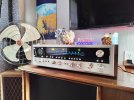
I know what you mean with the PCB quality being substandard, but it sure sounds nice and looks pretty!

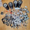
I thought some might like to see the carnage that came out of this thing - a sight to behold. This isn't even all of it!

A big thank you to everyone who helped me work out last few kinks! You are much appreciated
 

Attachments

  • IMG_20240117_164403.jpg
    IMG_20240117_164403.jpg
    124.1 KB · Views: 19
  • IMG_20240117_163503.jpg
    IMG_20240117_163503.jpg
    243.6 KB · Views: 19
Back
Top Bottom