

You are using an out of date browser. It may not display this or other websites correctly.
You should upgrade or use an alternative browser.
You should upgrade or use an alternative browser.
Crossover Calculator Design Question
- Thread starter PR Audio
- Start date
Register to hide this ad

Re is the DC resistance, crossover calculators want AC impedance. I would use nominal impedance.
bowtie427ss
Lunatic Member
The manufacturer's stated impedance is usually a nominal, or average of the impedance across it's rated bandwidth. Horn drivers, and tweeters will generally be fairly close to their nominal impedance in the crossover region. As the moving mass of the driver increases, so does the variation of it's impedance across the frequency spectrum. Woofers especially can have a pretty dramatic/dynamic impedance curve.
Ideally, you have a graphically represented impedance sweep of your drivers, and you calculate from the MEASURED impedance at the crossover frequency you're aiming for. Here's an example:
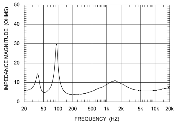
In the above example of an 8 ohm woofer curve, you can see that if you were aiming for an 800hz crossover point, the impedance would be right at 8 ohms or equal to it's nominal rating. But, if you were looking for a 1500hz XO, the impedance actually hits a peak centered just above 1500 of 12 ohms, a fully 50% difference.
Ideally, you have a graphically represented impedance sweep of your drivers, and you calculate from the MEASURED impedance at the crossover frequency you're aiming for. Here's an example:
In the above example of an 8 ohm woofer curve, you can see that if you were aiming for an 800hz crossover point, the impedance would be right at 8 ohms or equal to it's nominal rating. But, if you were looking for a 1500hz XO, the impedance actually hits a peak centered just above 1500 of 12 ohms, a fully 50% difference.
Last edited:

PR Audio
Super Member
The manufacturer's stated impedance is usually a nominal, or average of the impedance across it's rated bandwidth. Horn drivers, and tweeters will generally be fairly close to their nominal impedance in the crossover region. As the moving mass of the driver increases, so does the variation of it's impedance across the frequency spectrum. Woofers especially can have a pretty dramatic/dynamic impedance curve.
Ideally, you have a graphically represented impedance sweep of your drivers, and you calculate from the MEASURED impedance at the crossover frequency you're aiming for. Here's an example:
In the above example of an 8 ohm woofer curve, you can see that if you were aiming for an 800hz crossover point, the impedance would be right at 8 ohms or equal to it's nominal rating. But, if you were looking for a 1500hz XO, the impedance actually hits a peak centered just above 1500 of 12 ohms, a fully 50% difference.
Tox, thanks for your advise...Bowtie, thanks for such an educational, but simple explanation.


StimpyWan
Addicted Member
Typically, a tweeter is wired in-phase to the woofer, when using a first order crossover. For people sensitive to obsolute phase, and phasing issues, this can be a benefit sonically. But, peak power handling levels can suffer, since the tweeter is exposed to greater mid content, due to the shallow 6db roll off of the first order design. So, if you're not a head banger, try the simpler crossover. It could potentially sound better.
PR Audio
Super Member
Typically, a tweeter is wired in-phase to the woofer, when using a first order crossover. For people sensitive to obsolute phase, and phasing issues, this can be a benefit sonically. But, peak power handling levels can suffer, since the tweeter is exposed to greater mid content, due to the shallow 6db roll off of the first order design. So, if you're not a head banger, try the simpler crossover. It could potentially sound better.
Not a head banger, and for that I have a sub that fills in very nicely. I will try a 1st Order, not that expensive. I really like my cousin's 3-Way OB's, and they use a 1st Order. If doing a 2-Way 2nd Order, shouldn't I reverse polarity on one of the drivers, or that only applies to 3-Way crossover design?
StimpyWan
Addicted Member
Not a head banger, and for that I have a sub that fills in very nicely. I will try a 1st Order, not that expensive. I really like my cousin's 3-Way OB's, and they use a 1st Order. If doing a 2-Way 2nd Order, shouldn't I reverse polarity on one of the drivers, or that only applies to 3-Way crossover design?
Yes, with a second order crossover, the polarity is usually reversed, to that of the tweeter to the woofer. Three ways get a bit more complicated, and confusing. I've seen schematics, with just the tweeters reversed, or schematics with the mids reversed to both the woofer and the tweeter. So, I guess it's a try it every way, and see what you like kind of thing!
Also, with a first order crossover, you need a bit more listening distance, from the speaker, for the woofer and tweeter output to blend. Too close and you may hear the individual drivers, or the imaging might suffer. So, if it's a near field design, a 6db crossover may not work as well.
Good luck!

klipschorn
Klipschorn
Crossover calculator
My congratulations to you, Bowtie as you are the first I've seen, other than audio engineers, who recognize that fact. The impedance used should be that of the speaker at the desired crossover frequency.
In all my designs, especially for the woofer, I use the impedance of the driver in it's enclosure as the back loading of the cabinet will increase the impedance. The same is true for open back midranges when loaded into a sealed chamber. However, unless the crossover frequency is very low, below about 200 hz, the chamber loading on a midrange unit will have a much lesser effect.
This cabinet loading effect became very apparent decades ago when I was designing a pair of Klipsch type corner horns. The Klipsch design uses a 4 ohm woofer, (DCR~3.2 ohms). However, when loaded in it's sealed chamber of about 3 ft^3, the impedance rises phenomenally. In the horns I designed from scratch, a JBL 2205 was used. It has a nominal impedance of 4 ohms but when loaded as described above, it's nominal impedance rises to about 7.5 ohms.
The manufacturer's stated impedance is usually a nominal, or average of the impedance across it's rated bandwidth. Horn drivers, and tweeters will generally be fairly close to their nominal impedance in the crossover region. As the moving mass of the driver increases, so does the variation of it's impedance across the frequency spectrum. Woofers especially can have a pretty dramatic/dynamic impedance curve.
Ideally, you have a graphically represented impedance sweep of your drivers, and you calculate from the MEASURED impedance at the crossover frequency you're aiming for. Here's an example:
In the above example of an 8 ohm woofer curve, you can see that if you were aiming for an 800hz crossover point, the impedance would be right at 8 ohms or equal to it's nominal rating. But, if you were looking for a 1500hz XO, the impedance actually hits a peak centered just above 1500 of 12 ohms, a fully 50% difference.

twiiii
Lunatic Member
The impedance of the driver should be measured with it mounted in its enclosure at the frequency you are interested in. Enclosures can really change the impedance the amplifier sees. Some woofers the impedance will double and that goes for tweeters above 6 khz or so. Enclosures: using ports, labyrinths, folded horns, being very small in size or not damped by using lots of stuffing can change impedance, too. If you turn the sound level up to high the reflected pressure of the generated audio will cause the pressure on the driver cone to force up the impedance of the driver, too. Be it the back wave or reflected wave. Sound systems in large arenas are especially subject to loud crowd noises forcing up the impedance and sending back emf to the amplifiers.
bowtie427ss
Lunatic Member
Absolutely agree, and can think of a couple classic examples.Enclosures can really change the impedance the amplifier sees. Some woofers the impedance will double...........

Retrovert
Addicted Member
Absolutely agree, and can think of a couple classic examples.
Karlsons do this at multiples of the resonant frequency. Around an order of magnitude for the initial spike.
Transmission lines, which I thought would do more, are actually much more gentle, like a factor of 2-3 in the spikes.
What else does this in an impressive fashion?
(No diss intended on the Karlsons, BTW. I have a pair and like the sound.)
Retrovert
Addicted Member
Is there a way to calculate the impedance change imparted by the enclosure?
Yes. Akabak (and other design tools) will model it. I've never done this.