• The move to the new server is done. There are some software and database maintenance updates in process. This has us passing the hat around to help out. We appreciate any donations. Seriously, even a dollar helps. The payment page may be found here - https://www.audiokarma.org/support.html

Crossover caps, why use in parallel?

ziggydave

Active Member
Hi, a quick one for the techies amongst you.

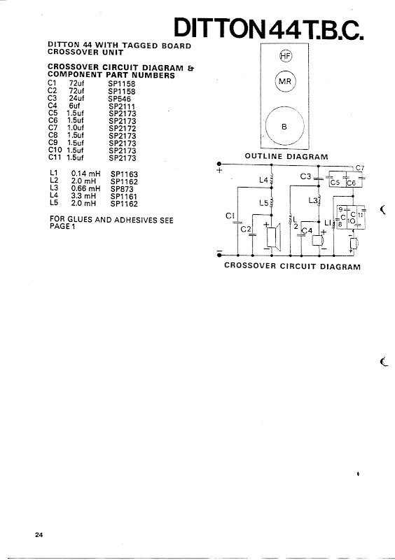
Checking over the crossovers in my Ditton 44's there are two instances where the manufacturers have used 2uF caps doubled and even tripled in parallel, to give 4 and 6uF respectively. These actually meter out at 6.9uF and 8.5uF so I think I should change them out. All the rest are very close or spot on.

Is there any reason, other than using up what they have in stock, for doing this pairing/tripling?

Secondly, they are currently metallised foil, should i use the same or will any good audio cap do?

Thanks for taking time to read this, I appreciate any help you can give me.
 
Register to hide this ad
The only thing I can think of would be to reduce parts inventory and shorten the BOM.
I've never done any kind of A/B comparison of capacitors so I don't have an opinion on that.
 
Does your crossover look like this:

Ditton44%20p3.jpg
 
Polypropylene film caps of your choice. No clue why they doubled up like that.
I use Dayton, Solen, Audyn and Mundorf aluminum&oil caps usually for crossovers.
 
I have a pair of Ditton 2ways that had 6 electrolytic caps in the crossovers.
One was 50uf! I replaced them all with film caps. The 50uf was difficult to find in a film cap that didn't break the bank. I did find a couple at Partsconnexion on sale. Instead of $50+ I got them for just under $5 in a close out sale. They were as big around as a small Campbell's soup can and half as tall.
 
Why use multiple caps? Perhaps??? size and space considerations, lower net cost, lower ESR, and as mentioned - it may be what they had. This isn't referring to bypass cap theory.
 
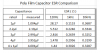
I'd have guessed ESR reduction as the motive, but for having recently explored the relationship between ESR, capacitance and frequency by measuring some caps with DATS V3.

ESR comp 1-4.png
Within this small sample range of 1µF to 4µF polypropylene caps there's a pattern of progression across and within each reference frequency.

ESR drops rapidly at first, then more gradually in an obviously non-linear fashion at 120Hz as capacitance increases.
ESR rises at a gradual rate with increased capacitance at 1kHz.
ESR drops at a very gradual rate with increased capacitance at 10kHz.

The bottom row result was surprising. I was expecting that 4 x 1µF caps in parallel would show less ESR than a single 4µF cap. Apparently it doesn't work that way. There was no significant difference.

Cost reduction and/or simplifying parts inventory could indeed be the reason. Though that raises the question of why a 6µF cap is used in the midrange filter while the tweeter has the same value made of paralleled caps. Perhaps the tweeter demands a more precisely tuned circuit? They may have juggled combinations of capacitor tolerance variances to arrive at tight target value. :dunno:
 
A cap is like a battery. The voltage across it is predictable, the current is determinate on other factors that vary with the application.
Parallel configurations reduce this variability and replacing electrolytic high value capacitors with non polar caps without the inherent chemical properties of electrolytics makes it viable since for resistors vs capacitors: 10R//10R= 5R and 10u//10u =20u. Good for us.
The question is the long term reliability of electrolyte vs film/polypropelene/etc. and if it matters. I vote non-electrolytic being that their use is nothing more than a cost saving venture.
 
Back
Top Bottom