nasinn
New Member
Hi all,
I recently posted this on the Lansing section and did not get much traction in my thread there, so I thought I would give it another go here.
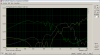
Essentially I picked up a pair of old JBL L65As and I am trying to evaluate if the crossover need some parts replaced or not. I recently got an oscilloscope / signal generator and had a bit of a play with one of the speakers. What I did was feed through my amp a sine wave of different frequencies and recorded the peak to peak voltages of the input terminals and of each of the driver terminals. The scope does not have one of these automatic response plot generator so it was a bit of a manual changing of frequencies and noting the Vpp values. With this Vpp information of the input vs. the drivers I calculate the voltage gain https://en.wikipedia.org/wiki/Gain_(electronics) plot, see below. One note is I don't think I was quite at the center of the brilliance / presence pads, but I can redo this all if there is any value in this sort of analysis.
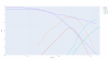
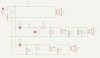
In addition to those measurements I also set up the crossover schematics in KiCad and ran a spice simulation of the frequency response and added to the plot results. I was a bit unsure on the L4 connection as the original schematic has some strange inductor symbol (I am not an electrical engineer - but my googling tells me its a tapped inductor but it was not clear to me where to connect the R7 to, but the sim did not ran when I connected it at the bottom of L4).
Not sure what the value of all this is, or if I was just keen on trying out the oscilloscope haha... My hope would be that this could give some indication of the state of the capacitors and the crossover in general so I can take an informed decision on what to replace if that is needed, so I am open to suggestion on how to interpret if at all possible the state of the crossover from the above.
Cheers,
Jonas
I recently posted this on the Lansing section and did not get much traction in my thread there, so I thought I would give it another go here.
Essentially I picked up a pair of old JBL L65As and I am trying to evaluate if the crossover need some parts replaced or not. I recently got an oscilloscope / signal generator and had a bit of a play with one of the speakers. What I did was feed through my amp a sine wave of different frequencies and recorded the peak to peak voltages of the input terminals and of each of the driver terminals. The scope does not have one of these automatic response plot generator so it was a bit of a manual changing of frequencies and noting the Vpp values. With this Vpp information of the input vs. the drivers I calculate the voltage gain https://en.wikipedia.org/wiki/Gain_(electronics) plot, see below. One note is I don't think I was quite at the center of the brilliance / presence pads, but I can redo this all if there is any value in this sort of analysis.
In addition to those measurements I also set up the crossover schematics in KiCad and ran a spice simulation of the frequency response and added to the plot results. I was a bit unsure on the L4 connection as the original schematic has some strange inductor symbol (I am not an electrical engineer - but my googling tells me its a tapped inductor but it was not clear to me where to connect the R7 to, but the sim did not ran when I connected it at the bottom of L4).
Not sure what the value of all this is, or if I was just keen on trying out the oscilloscope haha... My hope would be that this could give some indication of the state of the capacitors and the crossover in general so I can take an informed decision on what to replace if that is needed, so I am open to suggestion on how to interpret if at all possible the state of the crossover from the above.
Cheers,
Jonas

 In the mean time, listen and then ask old Lansing-heads over at the heritage site what to do for your parts & speaker. To measure each of your parts at the component level will require more gear (or at least more software) and you will ultimately need to measure speaker responses to know what it's really doing. Keep it fun and congratulations on your oscilloscope! You are metaphorically standing on the edge of an enormous and slippery slope--one false move and you will have 3 new sub-hobbies and you may not come-out for years (if ever). If you just want to restore the speaker and move on, that's another thing--do that, sell your scope, and run