


AVergison
New Member
Hello,
A part of my active 3-way speaker system is a 15" woofer (500 W) passively crossed over to a 6.5" mid (200 W) around 250 Hz, both 8 ohms. I was initially using a LR2 with two 10 mH ferrite core coils and two 39 uF capacitors in two LC circuits.
The fun begun when testing with tone bursts. At rather higher volume level (don't worry, I'm carrying ear protectors) I noticed a kind of rattle occurring below the crossover frequency. That made me think of bad speaker fastening. However, nothing felt loose, so I thought it would be the next logical step to check how the coils behaved.
It quickly turned out (by visualizing using a scope) that the woofer section coil entered saturation, so I purchased a 10 mH iron core toroid (donut) with low DC resistance replacing it, and results became better but not quite satisfactory.
As the toroid had a specification of 1,500 watts I decided to set up an extremely simple test as follows:
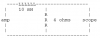
The oscilloscope was a single channel MBLE BEM-005 5 Mhz device (tubes only), dated, but still working normally. It's actually a remnant of my youth some 40 years ago...
The audio amplifier driving the circuit was a single channel of a DAP CX-2100 rated 2x 700 Watt RMS into 8 ohms and 2x 990 Watt RMS into 4 ohms.
The load consisted of eight resistors of 8 ohms / 50 Watt configured as a 4 ohms / 400 Watt load.
The input were sine bursts with a duty cycle of 20 percent (1 second of signal per 5 seconds).
The test input was a sine of 80 V peak, corresponding to some 800 W into 4 ohms.
I fed the circuit with 8 frequencies from 22 up to 270 Hz and here's the output I got: (taken with my mobile)
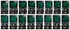
From left to right: input signal - 270 - 220 - 180 - 150 - 120 - 100 - 82 - 68 - 56 - 47 - 39 - 33 - 22 (twice, different time base) Hz.
The scale of the pics is 20 V/division.
It is clear that severe distortion shows up as of 150 Hz downwards.
For those who have interest, here are some signals measured over the coil:
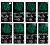
The scale of the upper four pics is 20 V/division, the lower pics have 10V/division.
Next test, and IMHO way more interesting, is a DUAL tone signal with 22 and 660 Hz of equal intensity.
The idea is that the 22 Hz passes virtually without attenuation, but the 660 Hz is attenuated with around 20 dB. We should see the big 22 Hz sine with a small 660 Hz ripple.
Here's what happens whenever the momentary voltage exceeds 40 volts:
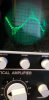
The small ripple is fine in the areas between + and - 40 volts. However, above 40 volts the iron core goes into saturation and is no longer a core. The coil becomes an air coil. Hence the inductance severely drops and the 660 Hz isn't attenuated anymore. What is especially bad is that the 660 Hz signal breaks through at the outer top and bottom sides in an asymmetrical way, causing a severe distortion.
After this experience I was wondering why vendors of coils with ferrite or iron cores don't provide saturation current as an indication of the limit of usability of the coil. The said toroid costing 50+ euros had a spec of 1,500 watts, suggesting that it could be used with drivers up to that power. In reality saturation starts at a current of 40 volts / 4 ohms = 10 amps, meaning something around 200 to 250 watts sine, only !!! Anything of input above that level will cause the woofer to receive heavily distorted midrange signals, and given the fact that the woofer has a 1,000 watts peak spec that just means that the crossover becomes totally unusable.
For now I didn't mention brands and part numbers, on purpose, we can always go into more detail later on. But I wanted to learn why inductors are enveloped in so much mysterious haze, up to becoming a cult, and about no vendor dares to tell what there products really are capable of. IMHO the maximum current before some given percentage of distortion (say 5 or 10 percent) is about all what counts, besides the DC resistance. I don't catch why vendors do specify maximum power (if they do). Into how many ohms? 2, 4, 8 or 16 ?
Oh, and how about the initial ferrite coils? Well, they started saturating at around 20 volts... or some 50 watts! Totally useless in the woofer section, ALTHOUGH I kept them in the mid sections as the peak current is way lower, and no noticeable distortion occurs.
Any similar experiences from you guys? I'm waiting for it before doing anything more with the woofer section coil. But I'm already seriously considering air coils, even if they are more costly and bulky.
Thanks,
Andre
A part of my active 3-way speaker system is a 15" woofer (500 W) passively crossed over to a 6.5" mid (200 W) around 250 Hz, both 8 ohms. I was initially using a LR2 with two 10 mH ferrite core coils and two 39 uF capacitors in two LC circuits.
The fun begun when testing with tone bursts. At rather higher volume level (don't worry, I'm carrying ear protectors) I noticed a kind of rattle occurring below the crossover frequency. That made me think of bad speaker fastening. However, nothing felt loose, so I thought it would be the next logical step to check how the coils behaved.
It quickly turned out (by visualizing using a scope) that the woofer section coil entered saturation, so I purchased a 10 mH iron core toroid (donut) with low DC resistance replacing it, and results became better but not quite satisfactory.
As the toroid had a specification of 1,500 watts I decided to set up an extremely simple test as follows:
The oscilloscope was a single channel MBLE BEM-005 5 Mhz device (tubes only), dated, but still working normally. It's actually a remnant of my youth some 40 years ago...
The audio amplifier driving the circuit was a single channel of a DAP CX-2100 rated 2x 700 Watt RMS into 8 ohms and 2x 990 Watt RMS into 4 ohms.
The load consisted of eight resistors of 8 ohms / 50 Watt configured as a 4 ohms / 400 Watt load.
The input were sine bursts with a duty cycle of 20 percent (1 second of signal per 5 seconds).
The test input was a sine of 80 V peak, corresponding to some 800 W into 4 ohms.
I fed the circuit with 8 frequencies from 22 up to 270 Hz and here's the output I got: (taken with my mobile)
From left to right: input signal - 270 - 220 - 180 - 150 - 120 - 100 - 82 - 68 - 56 - 47 - 39 - 33 - 22 (twice, different time base) Hz.
The scale of the pics is 20 V/division.
It is clear that severe distortion shows up as of 150 Hz downwards.
For those who have interest, here are some signals measured over the coil:
The scale of the upper four pics is 20 V/division, the lower pics have 10V/division.
Next test, and IMHO way more interesting, is a DUAL tone signal with 22 and 660 Hz of equal intensity.
The idea is that the 22 Hz passes virtually without attenuation, but the 660 Hz is attenuated with around 20 dB. We should see the big 22 Hz sine with a small 660 Hz ripple.
Here's what happens whenever the momentary voltage exceeds 40 volts:
The small ripple is fine in the areas between + and - 40 volts. However, above 40 volts the iron core goes into saturation and is no longer a core. The coil becomes an air coil. Hence the inductance severely drops and the 660 Hz isn't attenuated anymore. What is especially bad is that the 660 Hz signal breaks through at the outer top and bottom sides in an asymmetrical way, causing a severe distortion.
After this experience I was wondering why vendors of coils with ferrite or iron cores don't provide saturation current as an indication of the limit of usability of the coil. The said toroid costing 50+ euros had a spec of 1,500 watts, suggesting that it could be used with drivers up to that power. In reality saturation starts at a current of 40 volts / 4 ohms = 10 amps, meaning something around 200 to 250 watts sine, only !!! Anything of input above that level will cause the woofer to receive heavily distorted midrange signals, and given the fact that the woofer has a 1,000 watts peak spec that just means that the crossover becomes totally unusable.
For now I didn't mention brands and part numbers, on purpose, we can always go into more detail later on. But I wanted to learn why inductors are enveloped in so much mysterious haze, up to becoming a cult, and about no vendor dares to tell what there products really are capable of. IMHO the maximum current before some given percentage of distortion (say 5 or 10 percent) is about all what counts, besides the DC resistance. I don't catch why vendors do specify maximum power (if they do). Into how many ohms? 2, 4, 8 or 16 ?
Oh, and how about the initial ferrite coils? Well, they started saturating at around 20 volts... or some 50 watts! Totally useless in the woofer section, ALTHOUGH I kept them in the mid sections as the peak current is way lower, and no noticeable distortion occurs.
Any similar experiences from you guys? I'm waiting for it before doing anything more with the woofer section coil. But I'm already seriously considering air coils, even if they are more costly and bulky.
Thanks,
Andre


