• The move to the new server is done. There are some software and database maintenance updates in process. This has us passing the hat around to help out. We appreciate any donations. Seriously, even a dollar helps. The payment page may be found here - https://www.audiokarma.org/support.html

Curtis Mathis console tube stereo distortion issues from FAILED COUPLATES AT POWER STAGE.

sean sweeney

AK Subscriber
Subscriber
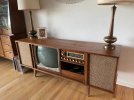
I had a repair job today, to fix this old console stereo. The owner said it was solid state but when I got there it was tube, so I had to run back and get my tube gear, so my van was completely full of gear to repair these things, but this one stumped me!

I've only run into this equipment very rarely, but it was a Japanese made tube chassis, Push Pull el34 stereo amplifier with television set and turntable, with tape inputs and some decent speakers. The complaint was it had a lot of distortion which the guy thought might have been the speakers. When I heard them I knew right away no that's regular old distortion!

So I noticed that both sides were equally distorted. I checked voltages and bias voltages, and try to figure out a reason for this intense distortion, which sounded like the unit itself was just constipated or something! The main filter caps weren't that bad, and the coupling caps were oil-filled, but they weren't that bad either!

I didn't have an oscilloscope with me of course, so I just took my trusty little miniature amplifier and clamped a clip onto the ground and took a coupling cap and used it as a probe to follow the signal from the preamp down to the amplifier.

The signal was crystal clear until it got to the phase inverter, which there was only one of, and now that I think about it how does that work? It was a 12ax7, but it was at that point that the sound went downhill. Has anybody worked on these and had the same issue? I really couldn't figure out why it was doing that.
I changed the coupling caps and the preamp tubes as well as the output tubes, and nada! Tested the speakers with my amplifier that I brought and they tested fine. It just sounded like the stereo had completely backed up somehow. As if something was draining all the power from it.

It wasn't particularly well made, cheap Japanese stuff, but nothing to equal the sound It was getting. Just curious if there's a reason that we know of? I have a second appointment to go back there and bypass the power section and put a solid state power amp in there to clear it up, but I thought maybe if someone knew what was up with these, as I've seen other people with this issue, and so maybe put it out there and know what it is!
 
Register to hide this ad
this reminds me of a plumber I called to fix a water leak, he showed up at my door with a pipe wrench and a plastic Home Depot shopping bag full of parts.

He gave me a price for the job and I said I'll think about it. Never called him back
 
this reminds me of a plumber I called to fix a water leak, he showed up at my door with a pipe wrench and a plastic Home Depot shopping bag full of parts.

He gave me a price for the job and I said I'll think about it. Never called him back
Yeah, well, be that as it may, I'm asking for input on what may be sapping the signal away from both sides of a stereo amp. I am the busiest and most capable tech in a major metro area, so, maybe peddle your derision on facebook, or insta... Let's see... don't have an answer... taking cheap shots at those who dare to ask! You must be a hit with the tweener girls! Lol.
 
got a model number and/or a schematic?

Most tube amp diagnostics can be done with a voltmeter honestly, generally if its really whacked out somewhere you'll see the DC voltages being wrong by a decent margin.
 
Sure, and none of them were out. I mentioned that in the second paragraph. That's why i started probing along the signal path. The signal stayed strong right up until between the PI and power tubes. It ad these odd looking packs of resistors and caps? Resin covered things they made in the early 60s, but they were all over, at each stage. I don't know what their purpose was, as there were other more standard caps and resistors. The weird thing is, that both sides of the amplifier sounded just as bad, nearly identical, but it would be inconceivable that both output Transformers went down at the same time, and I did a whole side of the amp, replacing coupling caps and tubes as well. Same thing. I mean I'm just kind of baffled by this. Nothing looks out of spec. Just sounds terrible! I have a feeling it's something to do with of those modules, each with about six leads coming out of them. I think they're specialized for different parts of the amp, as there were a couple of them up on the base and treble controls, obviously more tone-related, but I would feel odd removing them. I did clip the leads off of one in the vicinity of the phase inverter and power tubes, on the one I was working on replacing everything, but it still made no difference! So, I guess if someone is familiar with these particular amps they'll have an idea. It's just not any of The Usual Suspects here.
 
got a model number and/or a schematic?

Most tube amp diagnostics can be done with a voltmeter honestly, generally if its really whacked out somewhere you'll see the DC voltages being wrong by a decent margin.
Ok, i think i found the gremlin. 6 pin couplates, made by centralab and sprague. Containing carbon resistors and coupling caps, made specifically for amps like this. They both looked heat damaged. I tried to find the schematic... but i didn't have enough info... just found a few links that mentioned these things. Looks like a pretty chintzy thing to put at the power stage, imo. Also kind of hard to suss out, as the values inside have to be sussed out and replaced with standard components. I had a feeling. Well, it was actually obvious, i guess i just wanted to hear someone else say it! Lol. Uugh. Ok... that's the prob...
 
yea those can be a problem, if you are lucky the schematic will have an internal diagram showing the values. If not, it will have a part number you can look up, if you're totally SOL then you just have to make best guesses based on what you can determine the basic arrangement should be and sane values from other circuits.

also EL34 or EL84? EL84 would be more typical for this sort of thing.

personally I wouldn't sub this with solid state, I'd fix the tube amp.
 
Yeah, well, be that as it may, I'm asking for input on what may be sapping the signal away from both sides of a stereo amp.
well, these threads are read by and help others who may want to learn something.

Without you posting a schematic, it's impossible for anyone unfamiliar with your particular amp to gain some knowledge from this thread. You didn't even post a model number.

The idea of a "forum" is not just to help one individual.
 
Ok, i think i found the gremlin. 6 pin couplates, made by centralab and sprague. Containing carbon resistors and coupling caps, made specifically for amps like this. They both looked heat damaged. I tried to find the schematic... but i didn't have enough info... just found a few links that mentioned these things. Looks like a pretty chintzy thing to put at the power stage, imo. Also kind of hard to suss out, as the values inside have to be sussed out and replaced with standard components. I had a feeling. Well, it was actually obvious, i guess i just wanted to hear someone else say it! Lol. Uugh. Ok... that's the prob...
Can you post a picture of one of those? I'm just curious. They sound kind of like PEC's? I've made my own PEC's before to replace the originals that had drifty carbon comps inside.
 
 
Last edited:
PEC: Packaged Electronic Circuit. Caps, resistors, etc in one epoxy covered device.

1791479523075.png
This is what it looks like on a schematic (Eico HF-32):

1791479199760.png

Everything within the dotted lines is contained in the PEC.
 
Last edited:
 
The signal was crystal clear until it got to the phase inverter, which there was only one of, and now that I think about it how does that work? It was a 12ax7, but it was at that point that the sound went downhill.
I was kind curious about this- only one phase inverter in a stereo amp? Could the two triodes of the 12AX7 each be a phase inverter for one channel? I'm assuming this was a "split load" type PI? Usually not arranged that way, but a problem around that one tube could affect both channels.
 
need at least one triode for an inverter, could be one twin triode tube shared between 2 channels though. Can't use one inverter for 2 channels thoug.

If we really want to get into the bad old days, there are ways to do this without an inverter at all. Transformers are one way, but there are some distinctly horrible methods too. Circa 1940 Philco radios used a large screen resistor on one tube with a coupling cap from the screen to the grid of the other tube in the pair. The idea was that voltage drop across the screen resistor thanks to screen current draw produced an AC voltage out of phase with the signal coming into the grid, and if you got the resistor ratios right it would work to feed the grid of a second tube. Strictly speaking it does function but the balance is terrible.

Another way I've seen was to operate the output stage basically as a long tail pair. The grid of one output tube is grounded, and both cathodes are tied to a common un-bypassed resistor. That one should be less terrible than the screen thing but the "tail" is usually too short to get really decent balance unless there is a lot of extra HV to burn and the grids are biased from a tap in the chain.

then you get those goofy push-pull mono / SE stereo things that need an out of phase phono cartridge to work and usually have 3 output transformers.


but more likely its just one tube with two triodes shared between two channels.
 
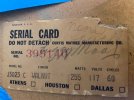
Thanks! Yeah, i tried to hunt up a schematic from what the guy sent me. He said it said solid state on the console, but when i got there, it of course was TUBE. So i had brought a ton of gear all aimed at repairing a SS console from '62, which CM did make, so my whole stash of germanium and caps for SS... i then had to go back and get all the tube supplies, and tried to locate a schematic, when i used the AI bots, they pointrd me to a photofact, which i purchased for $22... that wound up being a ZENITH TURNTABLE... so i was kind of PO'd at that point. There are very few markings on the console, so i really can't tell what to look up. I would buy it, if i knew of a 62 schenatic with stereo el84's.... and sorry if said el34s earlier! LOL. My bad. I'll include the pictures that I got in the beginning, and if anyone can lead me to a schematic I'll buy it and put it on here.
 

Attachments

  • IMG_20261007_203626.jpg
    IMG_20261007_203626.jpg
    143.9 KB · Views: 17
  • IMG_20261010_135158(1).jpg
    IMG_20261010_135158(1).jpg
    101.2 KB · Views: 17
  • IMG_20261010_135208(1).jpg
    IMG_20261010_135208(1).jpg
    116.8 KB · Views: 17
Need a model number, but most of the early Photofacts can be found at archive.org, trick is knowing which set and folder is needed. can find that from samswebsite, then go to archive.org and pull up the set, flip through it until you get to the appropriate folder.

likely its by chassis number, but it could be console model number too.
 
A.I. Says that the different chassis (TV and tuner) were made by different companies, so you want to look up the service literature based upon the particular chassis number rather than the furniture model. The amp/tuner chassis may have a tag or a stamp on it with "28A2" or "28B" and that would likely lead to the proper schematic. This vendor offers a Sams (622 folder 8) for those models, and you can also find those folders pretty cheap on Ebay, etc.
 
A.I. Says that the different chassis (TV and tuner) were made by different companies, so you want to look up the service literature based upon the particular chassis number rather than the furniture model. The amp/tuner chassis may have a tag or a stamp on it with "28A2" or "28B" and that would likely lead to the proper schematic. This vendor offers a Sams (622 folder 8) for those models, and you can also find those folders pretty cheap on Ebay, etc.
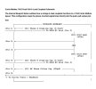
Yes, thanks. I didn't see the info on it when i looked. This one that i found is the closest one, as it has 12ax7 tubes and EL84 power tubes. It has two for individual channels, that go through a basic tone section then straight down to a single 12ax7... with two coupling capacitors coming off the 12ax7 PI, to each of the two el84's. It's down at that point where it picks up distortion, via the couplates. I asked the ai bots and they seem to think that the 6 pin couplates they used were these ones that they made a schematic for... I'll post a pic of that as well, as it's likely as close as ill get today. Still wondering how the one tube was the PI for both, but on my old hammond amp, i remember the PI was taken from the plate on one side, and the cathode on the other for the phase inversion. I guess that could work here?
I have a feeling the driver tube handled the output and the couplate reversed the phase, possibly. So this may be right or wrong... but the weird thing is I only remember seeing one couplate... plus somebody had at one point replaced some coupling capacitor with a newer molded one from the mid-60s.
 

Attachments

  • PSX_20261010_151345.jpg
    PSX_20261010_151345.jpg
    129.4 KB · Views: 8
  • Screenshot_20261010_153344_Word.jpg
    Screenshot_20261010_153344_Word.jpg
    62.9 KB · Views: 7
Back
Top Bottom