• The move to the new server is done. There are some software and database maintenance updates in process. This has us passing the hat around to help out. We appreciate any donations. Seriously, even a dollar helps. The payment page may be found here - https://www.audiokarma.org/support.html

Curve traces for power transistors NMA1012, NMC1012 2SA1116

JoseHH

Super Member
Hello Audiokarma community,

I know that this thread may have come too late to be useful, but I have not seen this information posted so I went ahead and started this thread. I have some power transistors that I removed from a Sansui AU-D907 because I bought this unit with a mix of different types of transistors and with only one complementary pair per channel. But there were two NMA1012 and one NMC1012 transistors in working order. I decided to make some good use of these working transistors and decided to measure their collector characteristic curves.
There is another thread that show curves for power transistors but the tests were done at very low collector currents. Thus, built a curve tester from a kit that is available online, and with some modifications I was able to get a +/- 18 volt range for Vce and collector currents of 1 A. The device under test (DUT) is driven by a triangle wave for each base current step. On the emitter of the DUT there is a 1Ohm sense resistor connected to ground which is used to get an estimate of the collector current. This curve tracer connects to an oscilloscope in mode X-Y. The base currents in the sequences of curves that I attach correspond to 0.0mA, 1.5mA, 2.85mA, 4.20mA, 5.4mA, 6.5mA, 8.0mA and 9.2mA. These were obtained by measuring the voltage drop across a 100 Ohms resistor (1%, 1W) connected between the base and the emitter. I used the oscilloscope to measure these voltages and then converted them to currents using Ohm's law.PNP_Cal.jpg

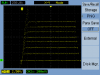
Here is the calibration for the PNP case(yellow is the base signal), and the nearly triangular waveform for the collector (green).
Next is the data i got for the NMC1012 NPN transistor.
nmc1012_5.jpg
The hfe at 10 Volts and Ib=9.2mA is hfe=1.03A/0.0092A=112.

The next figure is the data for the NMA1012. The base currents have the same magnitude as those for the NPN part but with negative values. I get a value of hfe=98 for this transistor.
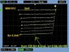
nma1012_5b.jpg
The next is a 2SA1116 transistor which was also in the AU-D907 that I repaired: The curves are collected sequentially and in this image the scope did not capture completely the second curve for Ib= -1.5mA. For this 2SA1116 the hfe at -10V and Ib=-9.2mA is 106.
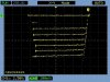
2sa1116_5b.jpg

The results are in a rather low current and voltage zone but nevertheless, they are quite nice to see since there is no datasheet for these parts. I also measured the 2SA2223A and 2SC6145A TO-3P modern replacements, under the same conditions for sake of comparison. This data is available in the datasheets.
2SA2223A:
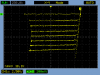
2223A_5.png


2SC6145A:
2SC6145A_5.png
 
Register to hide this ad
That's odd. My meme got spiked.

Oh well...Yes the evil insect rubbing claws saying "Good" was sincere.


giphy.gif
 
Last edited:
I think Ron means "Good Work"!
I built a curve tracer kit From that auction site that is for "small signal" transistors, and always figured that it could be scaled up for power transistors. So I'm quite interested to know what kit you started with, and how you modified it to work in the ±18v range.
 
Hello Steve,

I bought this kit (see attached schematic) which i used as the main board. I added another board. The modifications are as follows:
1-Instead of the 5.6V zeners I used 10 V zeners. This puts the CD4024 at it maximum operating voltage but also it allows to extract the largest current from the IC (10mA in theory) . I put a switch on the front panel of my tester so I can switch to the original zeners fo the original functionality of the tester is preserved for the case of small signal transistors.

2-Modify the the 2-2R current digital to analog converter to allow more current. Namely replace the 5 7.5kOhm resistors with 3K resistors.

3-Change the supply voltage from regulated +/-15 to regulated +/-18V. I used a 18V-0-18V transformer rated at 3 A. The regulated board used the MC7818 and mc7918 voltage regulators.
With these modifications the kit can span an ca. 10V range for the Vce but the protection circuit built in triggers and stops the waveform. Thus the kit with these modifications can not be used to test driver or power transistors but it may be used to test small signal transistors. In my opinion there is no point in modifying this part of the kit because i want to have it for eventual testing small signal transistors which should be protected from damage during the test.
The modifications continued as follows:

4-The original kit drives the collector via a push-pull BD139/BD140 pair . From the main board at the point where the wire used to go to the collector of the DUT i connected a wire to a daughter board that contains an lm741 buffered with a pair of darlington transistors TIP122/TIP127. The op amp is configured as a non inverting amplifier with a voltage gain of 2.
The output of this board goes to the collector and it also wired to a BNC connector that goes to the channel that provides the horizontal axis (X) of the oscilloscope. This board is powered from the rectified and filtered but unregulated voltages (measured +/-23V unloaded) taken from the power supply right from the filter capacitors prior to the regulators mentioned in 3.

5- I used a 2W 1.00ohm 1% from the emitter of the DUT directly connected with a cable into the center tap of the transformer. The tests current return to that point to prevent fluctuations in the ground potential. The collector current is measured across this 1Ohm sense resistor, so 100 mV in the oscilloscope means 100mA across the DUT.
Notes:
The triangular wave is not perfect. It clips at the bottom when driving pnp transistors, i still need to fix this. But in the x-y mode the waveform that drives the collector does not affect the shape of the curves.
The darlington pair as well as the DUT must be on heatsinks.
The diodes in the power supply i used were 1N4002, but it may be better to change them to 1n5402 because with the darlington pair the current on the DUT could exceed the 1A rating for the 1N4002.

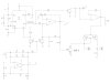
Also, please note that there is no protection for the DUT. But i built this to test driver transistors that i bought to see if they are fakes. So they should better withstand an amp or more at +/-18V. I do not care if i destroy fakes, since they are meant for that after all. I attach the schematic of the main board in it original form and the schematic of the daughter board. I can send you the cad files if you want to make a PCB.
A final note on the purpose of all this. The original goal of this tester was to see if some parts i bought are genuine. I tested many transistors and it seems like the collector curves my be used as a fingerprint for the transistor. Here in Bangkok there are many shops that sell NOS parts and by testing them i am finding that many of them are not fakes. I am building another tester to drive the transistors with DC but at a VCE of 140V, to see if they can provide several tens of mA close to their SOA border. If it works and if there is interest I will post the details somewhere.

Jose
 

Attachments

A final note on the purpose of all this. The original goal of this tester was to see if some parts i bought are genuine. I tested many transistors and it seems like the collector curves my be used as a fingerprint for the transistor. Here in Bangkok there are many shops that sell NOS parts and by testing them i am finding that many of them are not fakes. I am building another tester to drive the transistors with DC but at a VCE of 140V, to see if they can provide several tens of mA close to their SOA border. If it works and if there is interest I will post the details somewhere.

Sounds like a very handy device. Seriously putting this on the "make one" list.

The DC one sounds very handy too.
 
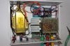
Here are pics of the of the curve tracer PCAs & P/S I got on fleabay. Looks like I never finished the schematic. The curves are displayed on my 468 scope. I had to add some BNC connectors, and used an R-core transformer to feed it.
I was happy with the results, but was really more interested in output transistors and always figured the design could be beefed up. Sadly, it is another project that I have let slide.

P1040768A.jpg


Tr Curve Tracer Schematic.jpg

P1040781-S.jpg
 
Here are pics of the of the curve tracer PCAs & P/S I got on fleabay. Looks like I never finished the schematic. The curves are displayed on my 468 scope.

Steve,
That is exactly the same circuit of the kit i purchased. I have the same power supply board as you do. I believe all of these are made here in Bangkok. But the idea was originally posted in an electronics magazine. Now I could not locate the site :mad:.

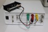
But you are right it needs to be beefed up. The way i used to increase the currents for driving the base of the DUT is a brute force approach. Ideally another buffered opamp should be used there and leave the board from the kit untouched. For driving the collector-emitter junction, the approach i used is acceptable. Actually the lm741 chip is being operated beyond the maximum allowed for the rails. But It still runs cool as it job is to drive the base of the darlington where I used two 2.5k resistors from pin 6 of the opamp to their respective bases. In the end I ended using a potentiometer as a feedback resistor so I can adjust the VCE range from 9 to 18 volts. It works really nicely.
Curve_tracer_small.jpgCurvetracer_Front_Small.jpg

For making the PCB i use a little shop here that takes the pcb file from altium and fabricated the boards. No solder mask no top overlay. Please see the picture below.
Buffered-Opamp_Small.jpg
With the kit it is much easier. You are very close to getting your expanded curve tracer.
 
My bad! I did not see the second schematic in your first post. Now I need to do a little studying.
 
My bad! I did not see the second schematic in your first post. Now I need to do a little studying.
Steve,
The second schematic is the kit. You already have this. The first schematic is my modification #4 which is the PCB i posted above. If you want to see the original source for this curve tracer please read the following attachment.
 

Attachments

A final note on the purpose of all this. The original goal of this tester was to see if some parts i bought are genuine. I tested many transistors and it seems like the collector curves my be used as a fingerprint for the transistor. Here in Bangkok there are many shops that sell NOS parts and by testing them i am finding that many of them are not fakes. I am building another tester to drive the transistors with DC but at a VCE of 140V, to see if they can provide several tens of mA close to their SOA border. If it works and if there is interest I will post the details somewhere.
@JoseHH
Really interesting!!
Did you ever come to build the tester to test at VCE from 140 Volt?
I was also wondering if you ever tested the Chinese legit versions from for example Inchange (ICS) that makes, I don't know if they are copies or they bought the licence to make them, the older types of for example Toshiba sc2238 which you mentioned in my thread of the au d907. (https://www.electro-andijk.nl/index...a/transistors/2sc/2sc2238-transistor-detail)?
 
Did you ever come to build the tester to test at VCE from 140 Volt?
I did not test the collector curves up to 140V. I was building a curve tester for up to 36V and a couple of amperes but my design had a flaw do I suspended that project. I can pass you the schematic if you want and point out where my design fails if you want. May be you can modify it and get a better curve tracer.
I came to realize that if a part was fake it will detonate when subjected to a voltage close to that in the rails of the amplifier. When I needed to replace the drivers in my AU-D907 needed to be sure that the parts i was going to use can withstand the currents that are stated in the SOA plot of their datasheet. So tested a series of parts that I purchased in Bangkok to determine if they were fakes, which included the 2SA1011/2SC2344, 2SA1837/2SC4793, 2SA1930/2SC5171 and a few others) I decided to rise the VCE to about 130V and see if the parts would blow when driving a collector current equal to that shown at that voltage in their datasheets. I used the CW line in the SOA plots at 130V except for the 2SB537 which if i remember correctly I tested at 110V. I did not post the results because I lost my notes.
I built a tester based on an idea that was originally posted in another forum. Please see posts #43 and #45 in this thread where I shared the schematics I used and where I state where I copy this idea from.
I observed curve traces for all these parts, with the tester you see here, and together with the SOA tests and HFE values. I remember that for the 2SC5171 i was also looking at the capacitance of each junction of the transistor using the chinese transistor tester and noted that you get quite close to the 16pf (i believe it was the base-collector junction what i was looking at). According to all these measurements, I concluded that most of the parts I bought were not fakes.
I actually was trying to find a way to measure the transition frequency to determine if my parts are fakes or not. So far what I built (not my design) works reasonably well if used to compare unknown origin parts with known authentic parts but I can not get an absolute measurement. I will post this somewhere in this forum when I have the chance.
 
Last edited:
Hello Jose,
It is never too late to make a post that can help others overtime! Thanks for posting this.
I have got an AU-D907 which has output transistors leaking on one channel. I wonder if you could help me telling me what are the best replacements available I can get and if there is any wiring that needs to change. I sent the amp to a local technician and he is really struggling to find replacements.

Any info would be greatly appreciated!

Regards,
David

Hello Audiokarma community,

I know that this thread may have come too late to be useful, but I have not seen this information posted so I went ahead and started this thread. I have some power transistors that I removed from a Sansui AU-D907 because I bought this unit with a mix of different types of transistors and with only one complementary pair per channel. But there were two NMA1012 and one NMC1012 transistors in working order. I decided to make some good use of these working transistors and decided to measure their collector characteristic curves.
There is another thread that show curves for power transistors but the tests were done at very low collector currents. Thus, built a curve tester from a kit that is available online, and with some modifications I was able to get a +/- 18 volt range for Vce and collector currents of 1 A. The device under test (DUT) is driven by a triangle wave for each base current step. On the emitter of the DUT there is a 1Ohm sense resistor connected to ground which is used to get an estimate of the collector current. This curve tracer connects to an oscilloscope in mode X-Y. The base currents in the sequences of curves that I attach correspond to 0.0mA, 1.5mA, 2.85mA, 4.20mA, 5.4mA, 6.5mA, 8.0mA and 9.2mA. These were obtained by measuring the voltage drop across a 100 Ohms resistor (1%, 1W) connected between the base and the emitter. I used the oscilloscope to measure these voltages and then converted them to currents using Ohm's law.View attachment 1149493

Here is the calibration for the PNP case(yellow is the base signal), and the nearly triangular waveform for the collector (green).
Next is the data i got for the NMC1012 NPN transistor.
View attachment 1149495
The hfe at 10 Volts and Ib=9.2mA is hfe=1.03A/0.0092A=112.

The next figure is the data for the NMA1012. The base currents have the same magnitude as those for the NPN part but with negative values. I get a value of hfe=98 for this transistor.
View attachment 1149503
The next is a 2SA1116 transistor which was also in the AU-D907 that I repaired: The curves are collected sequentially and in this image the scope did not capture completely the second curve for Ib= -1.5mA. For this 2SA1116 the hfe at -10V and Ib=-9.2mA is 106.
View attachment 1149504

The results are in a rather low current and voltage zone but nevertheless, they are quite nice to see since there is no datasheet for these parts. I also measured the 2SA2223A and 2SC6145A TO-3P modern replacements, under the same conditions for sake of comparison. This data is available in the datasheets.
2SA2223A:
View attachment 1149507


2SC6145A:
View attachment 1149508
 
Look at this site.
Sansui-vintage.com
Is reliable:
2SA1068, 2SC2493 Sansui used in High Speed Premium Amplifier, model AU-X1, but you can find them at Sansui AU-D907 Limited too, so they could be perfect choice for power output of AU919 (because AU-D907 Limited is Japan domestic model but it is the same as AU 919)
Good luck
 
I wonder if you could help me telling me what are the best replacements available I can get and if there is any wiring that needs to change. I sent the amp to a local technician and he is really struggling to find replacements.

Hello David,
You should start a new thread, so everything related to your unit will be in one place. It really helps everyone assisting you.
You can try to get the parts that @GrisPato suggests. They are the closest you can get. Alternatively, you can remove all the TO-3 transistors from both channels, (these may be sold and recover some money latter on) and install TO-3P modern transistors. The ones that have been tried in these amplifiers are the Sanken
2SA2223A/2SC6145A which you can still find in Digikey, and there are also the On Semi NJW3281G/NJW1302G
https://www.arrow.com/en/products/search?cat=&q=njw3281&r=true
https://www.arrow.com/en/products/njw1302g/on-semiconductor
What is available depends somehow on your location. If you are in Asia you can get some NOS parts from Japan, Thailand or Vietnam. If you are in Europe, Try GrisPato's suggestion. If you are in the US go with digikey and arrow, and there are a couple of other places where you can find modern parts.
With regards to the wiring, yes you can install screws and terminals to the power supply wires. Please take a look here post #19 where I quote this idea from Echowars. I have done it in my amplifier and I described it briefly here. I replied to another thread of yours, where I mentioned some of the restorations for the AU-919/AU-D907 where they explain what they do in some detail.
 
Last edited:
Look at this site.
Sansui-vintage.com
Is reliable:
2SA1068, 2SC2493 Sansui used in High Speed Premium Amplifier, model AU-X1, but you can find them at Sansui AU-D907 Limited too, so they could be perfect choice for power output of AU919 (because AU-D907 Limited is Japan domestic model but it is the same as AU 919)
Good luck


Thanks GrisPato! Are these direct replacements or there is anything that needs to be replaced in order to use these?

Have a nice day
David
 
Hello David,
You should start a new thread, so everything related to your unit will be in one place. It really helps everyone assisting you.
You can try to get the parts that @GrisPato suggests. They are the closest you can get. Alternatively, you can remove all the TO-3 transistors from both channels, (these may be sold and recover some money latter on) and install TO-3P modern transistors. The ones that have been tried in these amplifiers are the Sanken
2SA2223A/2SC6145A which you can still find in Digikey, and there are also the On Semi NJW3281G/NJW1302G
https://www.arrow.com/en/products/search?cat=&q=njw3281&r=true
https://www.arrow.com/en/products/njw1302g/on-semiconductor
What is available depends somehow on your location. If you are in Asia you can get some NOS parts from Japan, Thailand or Vietnam. If you are in Europe, Try GrisPato's suggestion. If you are in the US go with digikey and arrow, and there are a couple of other places where you can find modern parts.
With regards to the wiring, yes you can install screws and terminals to the power supply wires. Please take a look here post #19 where I quote this idea from Echowars. I have done it in my amplifier and I described it briefly here. I replied to another thread of yours, where I mentioned some of the restorations for the AU-919/AU-D907 where they explain what they do in some detail.

Fantastic I just saw this reply.
Many thanks for your input JoseHH!!
I'm in the UK so might try with GrisPato's suggestion.
Regards,
David
 
Last edited:
Back
Top Bottom