poorsolder
New Member
Greetings!
Long time reader, short-time lurker, first-time caller.
I have had a CX-600(R)for about 30 years, fronting a Kenwood Basic M1D. In the nineties to early oughts they drove a pair of floorstanding Infinitys from their low-sumer line that sounded just okay but could fill a sizeable warehouse space with impressive volume. I hope the kid I gave them to actually re-did the driver surrounds and enjoyed them. And me-now would like to apologize to all of my angry then-neighbors.
My partner preferred an NAD integrated amp (why are there two things to turn on? what button is for...? it's so LOUD! they are so scruffy-looking!), so the CX-600 has been hardly used for many years, and about 8 or 10 years ago it got wonky: massive drop in volume from disabling "source direct", noisy and unpredictable results from use of tone and balance controls, loudness knob increasingly resistant to being turned, and then loss of one stereo channel.
It now needs to become my daily driver so,
- Providing two stereo channels despite the marshmallowing power cap
- Tone and balance controls seem to be working just fine without a volume drop
- The loudness knob turns easily like the other pots but behaves like a master volume control: at FLAT there is sound, at the other end the amp is silent
- Have not done a full test of all of the ins-and-outs
- I ordered mundorf power caps of identical spec to those @Bratwurst7s used at @avionic 's suggestion.
- The pad on top of the transformer is, well, "crispy" is the best word I have for it. The top of the case is getting warm there, but can it conduct heat effectively in this form?
- Q407 seems of interest on both sides of the board, and Q403/406 on the solder side
- PCB is brown around the chip under the tape-out selector ribbon, although solder side doesn't look suspect to me.
Skills and tools
- I have always owned a soldering iron and been confident in using it--built a good bit of kit as a teen--but that confidence is probably overconfidence at the moment since I haven't soldered anything except appliance repairs in...20 years?
- My cheap mini soldering station is dead, I discovered, so I ordered a smart iron, i'll use the stand on the existing one, and hollow out the works for solder and tip storage.
- I have a solid if older and no-frills fluke meter with impedance and capacitance. theoretically also temperature, but the thermocouple lead spacing is identical to european wall plug spacing and thus my elder child fried it as a curious pre-teen (with no injury to child or property, thankfully) and I never replaced it.
- My electronics knowledge once exceeded simple circuits a bit, but does not any more.
Plan
- Replace the power caps. They are big and friendly to solder
- Clean the loudness pot again with kontakt 60 and isopropyl
- Lube all the pots with Kontakt 61
- Find the dang remote
- Desolder things for testing/replacement only where cost/benefit is high, such as preventing damage, extending usable life, ending world hunger. I am not chasing the moonrock needle.
- Try not to take on any more hobbies no matter how interesting. meaning don't move on to the AKAI AM-2280 next. or the celestion f3s you saw for 50€.
- See how the phono stage behaves when the TT arrives next week. I have an NAD phono stage I can use if needed.
Advice and help requested
- Ideas/suggestions on the loudness knob issue
- Should krusty the thermal pad be replaced with something? Any suggestions? I found 8mm thick alumimum rail in 60cm width, but the minimum purchase is six linear meters, and I need 48mm, so thats...125 preamps worth
- Important warnings about mistakes I am making or about to make
- Given that the cap nearest the transformer is the cooked one, is a heat shield of aluminum flashing worth it?
- (Politely) disabusing me of my ignorance
Kindly,
Mike

Long time reader, short-time lurker, first-time caller.
I have had a CX-600(R)for about 30 years, fronting a Kenwood Basic M1D. In the nineties to early oughts they drove a pair of floorstanding Infinitys from their low-sumer line that sounded just okay but could fill a sizeable warehouse space with impressive volume. I hope the kid I gave them to actually re-did the driver surrounds and enjoyed them. And me-now would like to apologize to all of my angry then-neighbors.
My partner preferred an NAD integrated amp (why are there two things to turn on? what button is for...? it's so LOUD! they are so scruffy-looking!), so the CX-600 has been hardly used for many years, and about 8 or 10 years ago it got wonky: massive drop in volume from disabling "source direct", noisy and unpredictable results from use of tone and balance controls, loudness knob increasingly resistant to being turned, and then loss of one stereo channel.
It now needs to become my daily driver so,
- I went to school by reading @Bratwurst7s multi-year CX-600 journey (I can't adequately express my thanks for that, but thank you!).
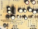
- I opened the case up for the first time ever the other day, and found that it was remarkably clean inside considering the life it has led. One of the power caps is a bit swollen on top, and there are some suspicious brown spots on the board, but not a crime scene.
- I cleaned out all of the pots with Kontakt 60, and rinsed them each with 1cc of 99.9 isopropyl in a needle syringe, which i discovered is 80% cheaper than the iso-in-a-spray-can.
- I still intend to lube them with Kontakt 61, but wanted to test and see if any deserved another cleaning before going there.
- I let the iso dry out a day, closed the case, connected it to the kenwood, set it to "source direct" (although I forgot to replace that button somehow
 ) and powered it up.
 - I asked the squeezebox to choose a song, and suddenly The Impressions were singing "Fool for You", and sounding great-- in both speakers!
- Providing two stereo channels despite the marshmallowing power cap
- Tone and balance controls seem to be working just fine without a volume drop
- The loudness knob turns easily like the other pots but behaves like a master volume control: at FLAT there is sound, at the other end the amp is silent
- Have not done a full test of all of the ins-and-outs
- I ordered mundorf power caps of identical spec to those @Bratwurst7s used at @avionic 's suggestion.
- The pad on top of the transformer is, well, "crispy" is the best word I have for it. The top of the case is getting warm there, but can it conduct heat effectively in this form?
- Q407 seems of interest on both sides of the board, and Q403/406 on the solder side
- PCB is brown around the chip under the tape-out selector ribbon, although solder side doesn't look suspect to me.
Skills and tools
- I have always owned a soldering iron and been confident in using it--built a good bit of kit as a teen--but that confidence is probably overconfidence at the moment since I haven't soldered anything except appliance repairs in...20 years?
- My cheap mini soldering station is dead, I discovered, so I ordered a smart iron, i'll use the stand on the existing one, and hollow out the works for solder and tip storage.
- I have a solid if older and no-frills fluke meter with impedance and capacitance. theoretically also temperature, but the thermocouple lead spacing is identical to european wall plug spacing and thus my elder child fried it
as a curious pre-teen (with no injury to child or property, thankfully) and I never replaced it.- My electronics knowledge once exceeded simple circuits a bit, but does not any more.
Plan
- Replace the power caps. They are big and friendly to solder
- Clean the loudness pot again with kontakt 60 and isopropyl
- Lube all the pots with Kontakt 61
- Find the dang remote
- Desolder things for testing/replacement only where cost/benefit is high, such as preventing damage, extending usable life, ending world hunger. I am not chasing the moonrock needle.
- Try not to take on any more hobbies no matter how interesting. meaning don't move on to the AKAI AM-2280 next. or the celestion f3s you saw for 50€.
- See how the phono stage behaves when the TT arrives next week. I have an NAD phono stage I can use if needed.
Advice and help requested
- Ideas/suggestions on the loudness knob issue
- Should krusty the thermal pad be replaced with something? Any suggestions? I found 8mm thick alumimum rail in 60cm width, but the minimum purchase is six linear meters, and I need 48mm, so thats...125 preamps worth
- Important warnings about mistakes I am making or about to make
- Given that the cap nearest the transformer is the cooked one, is a heat shield of aluminum flashing worth it?
- (Politely) disabusing me of my ignorance
Kindly,
Mike


 ,
,
 .
.