Hi all, I posted a short help notice in the general section yesterday, but maybe someone in this particular forum may have some extra information regarding the actual circuit diagram or manual info for the D707F Extra I have here, repairing/restoring for a friend. I do have the D9 manual, but the output and protection circuitry has differences and a circuit exclusively for the D707F Extra would be appreciated for clarity.
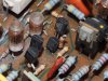
The D9 uses 2SA899/C2238 pairs, whereas the D707F I have here uses 2SA999/C2320 pairs (x2 per channel), except that one of the C2320 and A999 devices per pairing has a 820 ohm resistor soldered to the base. To add to the mix, the LC has a 2SA1091 in only one of the pairs, an replacement addition it seems, as it is vastly over-rated at 300v compared to the 50v A999/C2320 pairs, which look original, other than that A1091. The A899/C2320 pairs are 150V devices.
Bit of a mess for me without knowing what is actually supposed to be there.
Is there any definitive help among this group, please? Many thanks for good and welcome advice. I presume someone here has now or previously owned the (110V, in my case) D707F Extra.
The D9 uses 2SA899/C2238 pairs, whereas the D707F I have here uses 2SA999/C2320 pairs (x2 per channel), except that one of the C2320 and A999 devices per pairing has a 820 ohm resistor soldered to the base. To add to the mix, the LC has a 2SA1091 in only one of the pairs, an replacement addition it seems, as it is vastly over-rated at 300v compared to the 50v A999/C2320 pairs, which look original, other than that A1091. The A899/C2320 pairs are 150V devices.
Bit of a mess for me without knowing what is actually supposed to be there.
Is there any definitive help among this group, please? Many thanks for good and welcome advice. I presume someone here has now or previously owned the (110V, in my case) D707F Extra.