• The move to the new server is done. There are some software and database maintenance updates in process. This has us passing the hat around to help out. We appreciate any donations. Seriously, even a dollar helps. The payment page may be found here - https://www.audiokarma.org/support.html

Dahlquist DQ-10 crossover question

ddrjboo

AK Subscriber
Subscriber
I am refurbishing a pair of Dahlquist DQ-10s relying heavily on a previous post by @baco99 (thanks!). His thread is located here:

https://www.audiokarma.org/forums/index.php?threads/finally-dq-10s-in-da-house.513177/

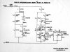
A schematic I got from classicspeakerpages is included below.

On one of my crossovers, the 0.5 mH inductor, was in poor condition. The spool that it used had one of the endcaps nearly completely broken off, and some of the wiring had slid into the crack between the cylinder and the endcap. I ordered replacement 0.5 mH inductors. I noticed that the resistance of the original 0.5 mH inductors is around 5 ohms. The resistance measured on the new inductors is about 0.5 ohms.
I have removed all of the inductor wire from the old spool, repaired the spool with hot glue, and rewound the wire onto the spool.

My questions are:

Is the difference in resistance between the old inductor and the new inductor going to be an issue, and if so, what would be a way to compensate for the difference?

Should I just use the repaired spool?

Thanks in advance for any advice!
 

Attachments

  • DQ10 crossover.jpg
    DQ10 crossover.jpg
    45.5 KB · Views: 65
Register to hide this ad
I am refurbishing a pair of Dahlquist DQ-10s relying heavily on a previous post by @baco99 (thanks!). His thread is located here:

https://www.audiokarma.org/forums/index.php?threads/finally-dq-10s-in-da-house.513177/

A schematic I got from classicspeakerpages is included below.

On one of my crossovers, the 0.5 mH inductor, was in poor condition. The spool that it used had one of the endcaps nearly completely broken off, and some of the wiring had slid into the crack between the cylinder and the endcap. I ordered replacement 0.5 mH inductors. I noticed that the resistance of the original 0.5 mH inductors is around 5 ohms. The resistance measured on the new inductors is about 0.5 ohms.
I have removed all of the inductor wire from the old spool, repaired the spool with hot glue, and rewound the wire onto the spool.

My questions are:

Is the difference in resistance between the old inductor and the new inductor going to be an issue, and if so, what would be a way to compensate for the difference?

Should I just use the repaired spool?

Thanks in advance for any advice!
Resistance of an inductor that size should never be 5 ohm. .5 sounds right. The resistance will depend on the gauge of the wire being wound. But it should not be 5 ohm.
 
Thanks for your reply. The new inductors are 20 awg (and I'm sure of better quality than the old), and the old inductors seem to be about 30 awg. Perhaps the condition of the old wire has caused the resistance to increase??
 
I measured again and am still getting 5.4 ohms on the old inductor. Is it possible that using the new inductor would just increase the gain on the tweeters, and that this could be adjusted using the treble potentiometer on the back side of the speaker?
 
Are you testing it outside of the circuit? It shouldn't matter, but it might. Disconnect from the circuit and test it. 30AWG wire will have a higher resistance, but 10x?
 
Yes. I haven’t taken the other crossover apart and it measures about the same value in the circuit.
 

Attachments

  • 4FFCF064-C76A-4694-A53A-730D1CF5B25E.jpeg
    4FFCF064-C76A-4694-A53A-730D1CF5B25E.jpeg
    77.4 KB · Views: 22
Yes. I haven’t taken the other crossover apart and it measures about the same value in the circuit.


Unusual..... In any case, I replaced mine with coils from PE and have run them beautifully for the last 8 or so years. I like the way they sound with the new coils, so hard to me to tell what changed when the coils changed.
 
Use the original! What they did by using 30 ga wire was to get a wire wound resistor
and inductor in one package. 30 is MUCH thinner than 20 and that explains the higher
resistance.
I take it you are talking about L5 on the super tweeter? That has very little program
power going into it and is there to shape the response, keep it the same.
 
Use the original! What they did by using 30 ga wire was to get a wire wound resistor
and inductor in one package. 30 is MUCH thinner than 20 and that explains the higher
resistance.
I take it you are talking about L5 on the super tweeter? That has very little program
power going into it and is there to shape the response, keep it the same.


Actually, Peter is right. I just looked ,and I did not change that one. I didn't recognize it at first because mine is wound differently.
 
In this case L5 is in parallel with the super tweeter so that high resistance makes sense. The DQ-10 crossover is an odd design, for sure.
 
Back
Top Bottom