• The move to the new server is done. There are some software and database maintenance updates in process. This has us passing the hat around to help out. We appreciate any donations. Seriously, even a dollar helps. The payment page may be found here - https://www.audiokarma.org/support.html

DDS-1/Altec crossover question. Do I have the HF comp circuit rendered correctly?

pete1729

Super Member
Well the DDS-1's are now in the living room, having been carried up by two men half my age. My original plan was to sell my Cornwalls and use the money to finance a full overhaul of the Seeburgs. My Craigslist ad got some interest but no takers at $800. The Cornwalls are fully sorted out and sound great so they're going to get a cosmetic update and will stay for now.

The Seeburgs are going to have to get sorted out on the cheap now.

I'd love to build Z-19 crossovers but that looks like $300 by the time all is said and done. The plan now is to just try to update the original crossovers. I have been down the rabbit hole for alternatives but I think I have a plan.

I think the original crossovers are an adaptation of the Altec N-800. I plan to copy the N-800F crossover and add the 30923 compensation filter. I'm going to use the original Seeburg inductors and the Dayton caps I soldered in there some years back, and add 16 ohm L-pads to them to replicate, in theory, the N-800F crossover. Then I'm going to add what I think is the 30923 circuit to that. Somewhere in my hunt for schematics I found a schematic for a 16 ohm 30923 and hand copied it into a schematic which I have attached below. Do I have this right? Will this tame the mid-range to not overpower the less sensitive bass drivers, will it give me a shot at getting a little more HF extension? I'm sticking with the 16 ohm drivers.

Thanks.
 
Register to hide this ad
HERE's a Good Thread on DD1 SEEBURGS

One participant used an 8 ohm 30923 but changed the cap to 3uF ( instead of 6uF ).
- That person didn't change the component values of the original crossover and was quite happy with the result.

Horn Circuit:

FWIW, the 16ohm version of the 30923 looks correct.

The 16 ohm variable LPad is wired wrong.
- You have the terminals ( orientation ) backwards, additionally, you won't need the 20ohm resistor that's going to ground.

In fact, you may not need the 16 ohm Lpad at all ( though you'll eventually find out one way or another once it's all built ).

Woofer Circuit:
Doesn't your DDS-1 have twin fifteens ( wired in parallel ) ?
Are they really 32 ohm speakers ( or are they 16 ohms each ) ?
- You might want to put a meter on one ( disconnected from anything else ) and get a proper dcr reading .

I'm doubting that the LF section of the N800G will work properly for those twin woofers.

Why not just replace the capacitors and keep the existing coils ?

Then add the 30923 midrange attenuator to smooth out the mids.

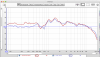
frequenzgang-seeburgs_608238.png
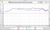
screen-shot-2015-10-21-at-18-47-54_608535.png

:)

PS;

index.php


Goodmans_h60958-3-60958c.jpg
 
Last edited:
I've read the Whaleman thread, but it's been a while since I visited there. The woofers do get called out as 16 ohm units and so the two of them in parallel present an 8 ohm load to the amplifier. The tag on the back instructs the user to hook them up to the 16 ohm taps of a Seeburg juke box, though. DCR readings were from 10.5 to 10.8 ohms. Using the existing coils is part of my plan, I figure they were spec'ed to match Utahs as they are wired.
 
HERE's a Good Thread on DD1 SEEBURGS

One participant used an 8 ohm 30923 but changed the cap to 3uF ( instead of 6uF ).
- That person didn't change the component values of the original crossover and was quite happy with the result.

Horn Circuit:

FWIW, the 16ohm version of the 30923 looks correct.

The 16 ohm variable LPad is wired wrong.
- You have the terminals ( orientation ) backwards, additionally, you won't need the 20ohm resistor that's going to ground.

In fact, you may not need the 16 ohm Lpad at all ( though you'll eventually find out one way or another once it's all built ).

Woofer Circuit:
Doesn't your DDS-1 have twin fifteens ( wired in parallel ) ?
Are they really 32 ohm speakers ( or are they 16 ohms each ) ?
- You might want to put a meter on one ( disconnected from anything else ) and get a proper dcr reading .

I'm doubting that the LF section of the N800G will work properly for those twin woofers.

Why not just replace the capacitors and keep the existing coils ?

Then add the 30923 midrange attenuator to smooth out the mids.

View attachment 2065470
View attachment 2065472

:)

PS;

index.php


View attachment 2065471

My rendering of the N-800F is flawed in that it does not show the whole stepped attenuation arrangement, the 20 ohm resistor is one of four steps wired into the circuit. The N800F values are likely to be unsuitable for the Utah woofers. Attaching the 30923 network to the existing crossover is entirely obvious now that you've said it, it was literally staring me in the face. I'm still curious about the other attenuation circuit that shows up in the N-1201 network and in Zilch's Z-19. Below is a schematic from his original M-19 mod.
 
The yellow appears to be an assymetric second order crossover for which I will use the existing DDS-1 network. The red part looks like the 39023 network, but what is the green part doing?
 
Well upon reading post #118 from this thread a little closer it appears to be a VHF attenuator circuit which will likely be unnecessary with the original 806A drivers I have in there.
 
Back
Top Bottom