• The move to the new server is done. There are some software and database maintenance updates in process. This has us passing the hat around to help out. We appreciate any donations. Seriously, even a dollar helps. The payment page may be found here - https://www.audiokarma.org/support.html

Defect Thorens TD-125 mk2. Motor is unsteady at 45

nurp

New Member
Hello

I bought ab defect Thorens td-125 and they don't know what's broken.
I didn't test if other speeds are correct with a phone. But it was not turning at 45 at all.

I changed those big capacitors with panasonic 25V1000UF. I don't understand much about electronics so it was my first soldering.

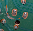
Also there was a crack on the board. I scraped the paths that the crack was cutting through and soldered. Continuity test passes. But Another question is, when I test continuity, the connector where it says A2 doesn't beep with the copper wires. I don't know if it's the connection I should be checking. But just the coppers on both sides of the crack beeps OK.
1780646583991.png

At 45 rpm, it's still turning unsteady, nothing changed:
All the cables are so old and looks like it was never serviced. I will change the audio cables, spray deoxit to connectors, oil bearings next.
 
Register to hide this ad
If you have continuity across your repair, but it doesn't read from your repair towards the left to A2, I'm going to say there is another crack somewhere that needs repair, or possibly its a coating on the board preventing good contact from the meter.
 
So if I scrape just next to A2 and test if that path is continues. Thanks for confirming that A2 is connected to that path.
 
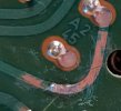
This part with the red line should all be connected. You should read low/no resistance from the scraped copper part along this path to the solder at the A2 end of things. Just make sure you scrape the solder pad just a little first, otherwise it may have some varnish blocking your connection.

1780682075034.png
 
I scraped and see where the signal breaks now. Do you think of I just drop some solder, it will make it continuous?
Nevermind, I did it and it works!!
 

Attachments

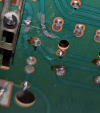
  • PXL_20260605_192843476.jpg
    PXL_20260605_192843476.jpg
    48.8 KB · Views: 9
Last edited:
Better to bridge it with a small bit of wire but I have patched cracks with just solder and had it work just fine.
 
I would bridge it with a small short chunk of bare copper wire.

A glob of solder might bridge it but the wire will connect the trace to the pad much better. A glob of solder might not look so good either. A touch of flux will help make nice looking permanent solder connections.

If the trace is messed up you can form a chunk of wire to copy the trace from point to point and solder each end and maybe a spot midway to keep the wire from moving or use insulated wire and just go point to point without worrying about what you jump over, in general.

Each repair takes a but of thought on how to do it ‘properly’.

Hope this repair gets you machine working right.
 
Do you think of I just drop some solder
You would want solder to be adhered to each side of the crack. This means you need to heat each side of the crack until solder flows before moving on. If you have good flow on both sides and a nice clean solder connection indicated by the continuous solder joint over the crack, you might be ok. This isn’t done by dropping solder on the crack. It may stick but might not be a connection.
 
Back
Top Bottom