• The move to the new server is done. There are some software and database maintenance updates in process. This has us passing the hat around to help out. We appreciate any donations. Seriously, even a dollar helps. The payment page may be found here - https://www.audiokarma.org/support.html

Defying the laws of POLARITY??

joestcyr

Member
3AE5FE68-6880-4F97-81FA-4FA7BBA6D6A1.jpegHey everyone, during my recap I’ve run into the usual values differing from the SM, but this one has me BAFFLED :no:. This is the F-2505 flat amp board. Pics show it; caps c09 & c10, both leads are soldered together? These are polarized 47uf 6.3v
This amp ran very well for years before I ever opened it.
How can this be? Any help greatly appreciated. J. DB9ED77C-0C86-4F6A-92B1-A689A25985AC.jpeg 821AE00D-85C1-4718-86D8-540BD0D7B7D9.jpeg
 

Attachments

  • F002DCF1-0D54-4300-8DB4-64F14F4DA09A.jpeg
    F002DCF1-0D54-4300-8DB4-64F14F4DA09A.jpeg
    81.3 KB · Views: 22
Register to hide this ad
need to look at schematic ..it may be a run of board errors early production and that was the fix .. just a guess ..
This serial Puts it in 1975 span. I’ve got large ground planes separated via dremel,?then a jumper connecting same ground. When I finish this beast I’lol post the photo history from beginning, thanks- will take a look @ schematic for sure.
 
my suspicions are maybe wrong but both channels being the same is hard to believe a mistake in soldering has taken place .
best i can say is leave it as it is seeing as it works .maybe someone can it through spice to see the difference .
 
Shortage of bipolar caps when the beast was built?

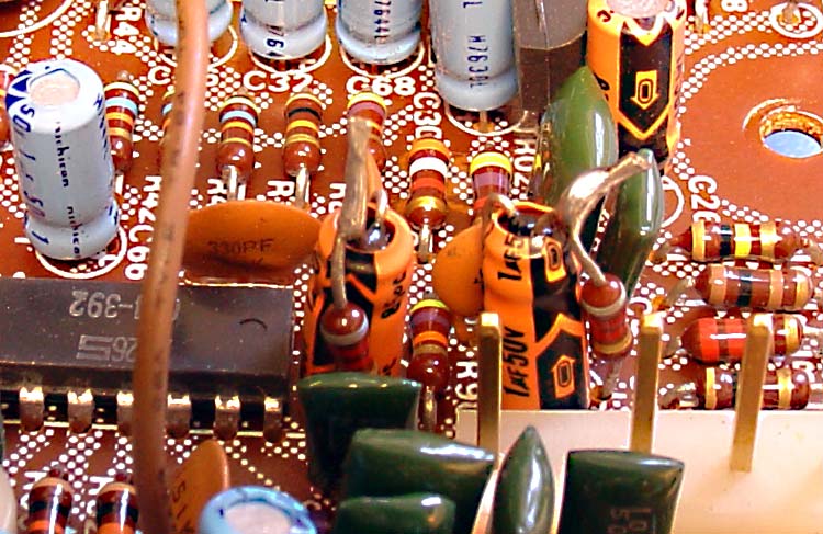
One of my favorite factory official kludge jobs ... Not enough room to add a dropping resistor to tweak the voltage, so they just put the caps in upside down and soldered the resistor to one of the cap legs ...

f2589-drop-resistors.jpg
 
True. With R19/C09 and R20/C10 being a parallel RC network on the emitters of TR07/TR08. Maybe it was doing the wrong phase shifting? Wrong impedance? Oscillations?
 
It's probably been mentioned, but never trust the screen printing on the boards OR the service manual completely. Keep careful track of each component and reinstall it the same way you found it if it had been working well prior to replacement. Exceptions to every rule of course ... I remember Trnsfmr of QRXRestore fame finding a cap that had been installed backwards on every QRX9001 built. He was able to see a significant increase in channel separation by reversing it.
 
Or to equalize. ?

Perhaps an odd way of making some sort of adjustment,
-and maybe not necessary a negative or "Cancellation" ? of an incorrect design,


I guess to most of us the best conclusion is to Ask,
and that's what the original poster did.

And to look at the pictures and to think of /Sansui installing those "Redundent"
Capacitors in a billion units,
I have to ask myself,

Why did they waste money on putting 2 capacitors in there for years
while wasting solder and wasting money instead of removing them in the first place with a ?

I would replace them as Sansui obviously paid money for you to own then 40 years later for a reason?

Or like my great grandaddy used to say,
No Harm No Foul

I Vote for spending the 33 cents each just like Sansui did.
?If This has been a part of Every board from Sansui and it has worked for 40 years
it/they were obviously there for a purpose.
Personally, I'm not one to try and out guess things that were there and
have worked for ~40~ years.
(well unless of course you can't afford the 66 cents that is.)
.

Moe,
“as it was” Is my mantra- this one I needed to hear from you and the audiokarma group for reassurance!
Am replacing all mentioned. Things I’m seeing defy logic, though at more than 3/4 through-hopefully no more surprises!
 
Don't forget to replace all the fusible resistors - the heat tends to kill those over the decades, and if they haven't failed yet, they're due. I had a couple that crumbled while extracting them. Same wattage metal film will do the job nicely.
 
Or to equalize. ?... I Vote for spending the 33 cents each just like Sansui did...
?If This has been a part of Every board from Sansui and it has worked for 40 years
it/they were obviously there for a purpose.
Nope! There's no equalization going on with the capacitors leads soldered together and the resistors become redundant, as the solder blob consists the path of least resistance. There's no adjustment or anything - the solder blob makes those components duds. The unit had worked for 40 years without R19/C09 and R20/C10 and wasting 33 cents (or whatever) in replacing them is plain nonsense. This is a TOTL AU-20000 unit and there were probably less than 20K ever made. Given Sansui and other contemporary Japanese mfgrs were purchasing electronic components from the lowest bidder by the hundreds of thousands, it makes sense to manually correct errors by assigning the temporary job to an employee, rather than modifying the production lines. They were not gods you know, and they did make mistakes, so perhaps stop worshiping them and have a look at the schematics.
 
Don't forget to replace all the fusible resistors - the heat tends to kill those over the decades, and if they haven't failed yet, they're due. I had a couple that crumbled while extracting them. Same wattage metal film will do the job nicely.
Skizo-How do I tell a fusible resistor?, where are they usually located in this amp?
 
They're usually green or brown with a matte finish, and will always be mounted high off the board for better heat dissipation. Most I've seen are located on the power supply boards and rail. Most will also have notches in the legs so you can only insert them so far - easy to add those to the new ones.

Yet another way to recognize them is to tap them with a screwdriver and see if they turn to dust ... ;-}

Burnt spots or discoloration is another good hint.

img_3939_copy-jpg.72137
 
Last edited:
Back
Top Bottom