• The move to the new server is done. There are some software and database maintenance updates in process. This has us passing the hat around to help out. We appreciate any donations. Seriously, even a dollar helps. The payment page may be found here - https://www.audiokarma.org/support.html

Denon DCD-2700 CD Player Mod Thread

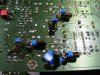
After having done all of that I got into a discussion with HypnoToad about adding a 0.1µF film cap across the supply lines of the op-amps to stabilize them and damp oscillations. I tried that first on a DCD-1290 and liked the results. There was a measurable drop in temp in the op-amps and another small improvement in overall clarity, including a little tighter bass. So I did the same to the 2700 units.

Actually I figured that if adding the film caps to the op-amps in tha analog section, would it be of use to add them to the op-amps in the digital section that are acting as motor controllers? It didn't seem like that it could hurt and so I added the 0.1µF/63v Wima MKS2 caps to all of the op-amps in the entire player.

View attachment 866802 View attachment 866803

I like this. Another incremental sound improvement. And when I was working on the 2nd player and paying a bit more attention I could see that the pcb was discolored from heat under all of the op-amps in the analog section. So I think that adding sockets for the op-amps might act as an additional bit of heat sinking to protect the pcb from heat damage, as well as the stabilization film caps.

Cheers,
James


Nice Job


But... 0.1µF film cap across the supply , in pin 4 and 8 ??? This is for single supply line, not dual.
If you got +12v in pin 1 and -12v in pin 4... then the decoupling is with two capacitors.... one in pin 4 to ground, and another in pin 8 to ground

I am wrong ??
 
Nice Job


But... 0.1µF film cap across the supply , in pin 4 and 8 ??? This is for single supply line, not dual.
If you got +12v in pin 1 and -12v in pin 4... then the decoupling is with two capacitors.... one in pin 4 to ground, and another in pin 8 to ground

I am wrong ??
Hi VRAudio and welcome to Audiokarma.

I apologize for taking so long to answer. Just in time for the new year I got sick with a really nasty cold. They were giving them away for free and I still didn't want one but got it anyway.

To answer your question, no, I don't think that you are wrong. But I'm still learning this stuff and have only just now started learning about the proper way to de-couple the supply lines on an op-amp.

It's interesting that you brought the subject up because the day before you posted I was reading the data sheet for the LME49720 and saw that TI used a parallel 47µF & 0.1µF cap to de-couple the op-amps in several of the circuit examples shown. And when looking at the schematics for my new-to-me Yamaha CD-S2000 I saw that this is exactly what Yamaha did for all of the analog section op-amps in the player.

Looking over the DCD-2700 schematic I saw that Denon made it easy for me concerning the op-amp positions that are important to me. Almost all of the op-amps in the analog section are actually only using one channel and the second channels are tied directly to ground.

So for positions IC315, 316, 317 and 318 pin-5 is tied to ground and for positions IC311 and 312 pin-3 is tied to ground. This let me keep the cap leads fairly short and was very easy to make the change. I used some Panasonic FM 47µF/25v that I had in my bench stock and soldered TDK MLCC-C0G/N0G 0.1µF/50v directly to the 47µF. From there it was easy to mount the cap sets to the back side of the board.

DSC06521.JPG DSC06522.JPG DSC06523.JPG

To be honest I haven't noticed any difference in sound quality. The player sounded fantastic before and sounds fantastic now. But I learned something new and feel better about things now. :)

Cheers,
James
 
OK. So a new development. I suppose that it might get confusing with me working on 3 different units and not all of them being up to the same level of mods. But, the only one that's still in my hands is unit-2. My son has unit-1 now and unit-3 is over in Arizona now.

Unit-2 was the least developed up until now. Over the last few weeks I've been bringing it forward. It now has the resister and ceramic cap swap, power supply 6800µF caps, general re-capping, bypass film caps on the outputs, op-amps and the op-amp de-coupling caps shown in the last posts. It does not have the psu voltage regulator mod. And up until a few days ago I deliberately hadn't changed the spindle motor.

Listening to it for a week revealed some general dirty sound, kind of ear biting irritating noise. So I pulled the mechanism and replaced the spindle motor & traverse mechanism plate. Going with simple finger wiggling it seems to me that the spindle motor on this one had more free play that the other units and especially so compared to the new motor. I deliberately did not replace the laser pickup.

So replacing the spindle motor cleaned up the sound considerably. But there is something that I have noticed on all 3 of these DCD-2700's and with every DCD-1290 & 890 that I've had my hands on. With some CD's there is just some level of distortion on the first few songs. But not every CD. I't's been very puzzling because it shows up even in the units with new spindle motors.

So a week ago I was just doing some general browsing and searching and I came across "Notes on the Troubleshooting and Repair of Compact Disk Players and CDRom Drives".
http://www.repairfaq.org/sam/cdfaq.htm
A very interesting site that I haven't seen before and to my surprise there is a section specifically dealing with the KSS240A and another concerning "audio whine". Read this!
http://www.repairfaq.org/sam/cdfaq.htm#cdsonywhine

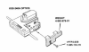
So for me this was extremely interesting to find that there was a resonance problem with these pickups and that Sony had made a damping weight and felt washer to deal with it. So the search was on to find the Service Bulletins and one of these weights & felt washers.

I have not found any hardware but after several days of searching I found a post at diyaudio that had one of the SB's. And it shows a drawing of the weight. I've uploaded this service bulletin to the AK database and I'm going to attach it here.

Cheers,
James
 

Attachments

So that was pretty exciting. No dimensions shown, but there is this for the screw: "+PTP2.6x8". That's something to work with.

I pulled an original screw and it measures 5.5mm long on the shank with a 0.8mm thread pitch. So if the replacement screw is 8mm long we can guess that the weight is 2.5mm thick. I also measured the hole in the pcb and it is 3mm dia.

That gave me something to start with. Looking at the drawing the hole in the weight looks larger than the one shown on the pcb and I made a WAG of 3.5mm and that the Japanese being an orderly and precise people that they had actually made the drawings somewhat to scale.

Sure enough taking a rule I got roughly 3.5mm dia measuring the drawing so I checked the other dimensions. I got a full width of ca 25-26mm and full height of ca 10mm not including the tabs shown. The cut-out on the lower right of the weight looked to be ca 10mm wide and 5mm high.

Screenshot_KSS-240A HFP0428 Service Bulletin.png

So next I found some scrap brass at work and set myself to making one of these weights to experiment with.

Cheers,
James
 
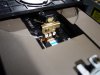
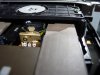
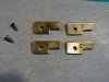
I found a piece of solid stock and hacked, filed & drilled my way to having a crude weight. And the dimensions can't be too far off because it fits! :):banana::)

Now, I didn't cut away the material on the upper positioning tabs like the drawing shows, and I didn't cut the slot shown on the bottom end of the mounting hole. So my weight is probably a bit heavier that the original. I actually made 5 of these things and weighed them with my little digital stylus tracking weight scale. The one that I ended up using (also the first one that I made) weighs 4.98 grams. 2 of them measured at 5.02 grams, and the other 2 were too heavy to measure because my scale maxes out at 5 grams. But this at least gives me at least a rough indication that the Sony weight is something under 5 grams.

DSC06542.jpg DSC06543.jpg DSC06545.jpg

Btw, I managed to find 2x 2.6x8mm screws in my bin of stuff cannibalized from some dead laptops. I'm looking around on ebay to try to find more.

Cheers,
James
 
Last edited:
I'll be the first to admit that the weights that I made are pretty crude. I'm thinking that finding some 10x10x3mm brass angle stock would be a better starting place than trying to hacksaw and file one of these out of solid stock like I did.

DSC06547.jpg DSC06548.jpg DSC06549.jpg

Cheers,
James
 
But wait! How about the most important part. Does adding the weight help with sound quality???

Well, I've only played 5 CD's so far but my cautious and tentative evaluation is, Yes.

I need to play a lot of different CD's but at this point my ears are telling me that it sounds overall a little better and so far I haven't found a CD that sounds ear scratching on the first few tracks. This evening I'm going to play Cracked Rear View from Hootie & The Blowfish because that's one that I recall that always sounds a little crappy on the first few tracks.

But this looks promising so far.

I haven't been able to find the 2nd service bulletin yet that I'm guessing deals with the felt washer. My understanding is that it is to be attached to the underside of the upper clamping disk. I'm still looking for more info on that. In a perfect world there would be an AKer that actually has some of these parts and would be willing to measure them. :)

Cheers,
James
 
So, moving on to my next subject. Since it looks like there are no more traverse mechanism plates with new spindle motors to be found is seems that the only solution to restoring an aging DCD-2700, 1290, 890 etc is to find a bare motor and replace them.

The motor is a Mabuchi RF-310T-11400 D/V5.9. And it turns out that they are all over ebay. So I'm going to order some from a couple of different sources and check them out.

Thinking it over I'm thinking that accurately and carefuly pressing the old motor from the spindle without damage, and them pressing it back on the new one at the correct height without bending the shaft is going to require making some jigs that I can use in a drill press will be a must. Alone getting the spindle at the correct height on the new motor shaft is the critical point. I have some ideas and will be working on putting something together. I'll post info when I get that far.

Cheers,
James
 
Lastly, I have finally found and bought an oscilloscope. It's a used analog Tektronix 2225 50mhz 2-channel dual trace. It arrived 2 days ago. The seller did a great job of packing, double boxed with full foam packing in each. It seems to work but I still have to learn how to use it and also build some to the hookup filters that Denon calls for in the service manual.

Lots of fun challenging stuff coming up. It will be great to finally do some measurements and be able to set focus and tracking.

Cheers,
James
 
So, an update.

It took me a bit of time to collect a new pair of probes and figure out the basics of hooking up and using the oscilloscope and making a set of hookup filters. Once I got there I first went through the adjustment and checking procedure on a DCD-1290 that I was preparing for a friend.

That went very well and the player sounded very good when finished so a few days ago I put the 2700 on the workbench and checked it out. Both focus and tracking gain were off and got adjusted. When I came to the eye pattern and checking the laser voltage the pattern looked good but showed a bit less than 1v-P/P. The spec is 1.2v-P/P, +/-0.3v. So I decided to change the laser.

I have the used laser that was removed from unit-3 and 4 new Chinese lasers. The unit that the laser was removed from was sounding great, the only reason that I changed it was that I didn't want to shop the player 7500+km to my brother-in-law with a used laser in it. Long way to make a house call. I decided that I would learn more from installing the used laser in my player and testing it than by going straight to a new one. It would give me the chance to test and evaluate the used one and build up some experience with this. If that didn't work out it only takes 15-20 minutes to swap the lasers.

The results were very interesting. The used laser tested at ca 1.1v-P/P. And this CDP now sounds fantastic. Absolutely great. Of the 3 units I would say that this one sounds best now. It throws an amazing sound stage. The focus and tracking adjustments along with the laser swap made a decided improvement in SQ. I'm extremely happy with how it sounds. So I'm just going to leave this laser in it for now and use it. I'll carefully evaluate the sound and put it on the bench every few months to check the laser strength to build up some experience of how long it takes for the laser to degrade.

I failed to take photos of all of this but it looks just like what happened with the 1290. Photos of that can be found here...
https://www.audiokarma.org/forums/i...player-mod-thread.688774/page-4#post-12468029

Needless to say I'm pretty excited about what having an oscilloscope on hand brings to the game. Pretty cool stuff.

Cheers,
James

ps: Oh. Last week I bought a defective DCD-3000. I think that I can fix it and will be starting a thread concerning that player soon. Should be fun.
 
Back
Top Bottom