
• The move to the new server is done. There are some software and database maintenance updates in process. This has us passing the hat around to help out. We appreciate any donations. Seriously, even a dollar helps. The payment page may be found here - https://www.audiokarma.org/support.html

Denon PMA 500V - persistent noisy right channel

redpackman

Active Member
I am working on a Denon PMA 500V Amp. It has a right channel that plays but is distorted. I don't believe it's the result of bad switches or pots as I've de-oxed all of them and when I fiddle with them the distortion doesn't change for the better or worse.

I wondered if the distortion was coming from the pre-amp "Processor" section of the amp (or however this amp is configured) so I disconnected the pre from the output ("Processor Out") section of the amp by pulling the jumpers.Then I connected the Processor Out" to another good Kenwood amp I have, and listened to the sound. Both channels sounded good.
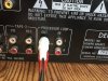
IMG_6169.JPG
So, not to jump to conclusions, I'm barely above a shade-tree self-taught tinkerer, what does that tell me? When I hooked up the "Processor Loop" jumpers again the distortion was back in the right channel. I remember working on a vintage HK amp that had a notoriously bad "noisy transistor" before and this sounds much like that sounded, but again, I don't want to jump to conclusions. The service manual and schematic for the PMA-500V is available online at HiFiEngine. Any suggestions you might have for me?

Let me add that I've replaced the A1358 transistor along with the power output pair 2SC2581 and 2SA1106 in the right channel. The distortion is the same now as before I replaced them.

I've got another issue setting the idling current on this which I've done on a lot of other units, but I'll deal with that elsewhere. IMG_6169.JPG
 
Last edited:
Register to hide this ad
Using the Processor Loop out jack on this unit only bypasses the input switching; the downstream components include all of the other preamp circuits (volume, tone, balance, loudness) and the power amp. So feeding Processor Out to another unit just tells you the input jacks and input selector switches on the Denon are fine. See the block diagram in the service manual.

To chase the problem I'd suggest that you first verify that all the voltages coming off the power supply are at their proper levels. This includes the rail voltages plus other supplies that are used for the ICs, etc. From a quick look, this includes ±18V, some +16.5V; perhaps there are others as well. Then I would check the DC offset at the speaker terminals, and the bias (idling) for each channel. I know you said you have a problem with the bias and you will deal with it later, but it could be involved in the distortion you are experiencing. If the bias is different in the L and R channels, feel the heatsinks after the unit is well warmed up, to see if they are heating up similarly.

If these things check out, I would next try systematically measuring voltages, starting from the speaker outputs and progressing upstream, comparing to the values given in the schematic and comparing the L and R sides, looking for significant differences. The schematic is well marked with voltages.

You didn't say why you replaced the output transistors, or 2SA1358. Or why you replaced 2SA1358 but not its complement 2SC3421. If this unit had shorted outputs on the right channel at some point, it is wise practice to replace the transistors upstream (i.e., 2SA1358 and 2SC3421), even if they are undamaged. But if they were damaged, you should look one step further upstream, and replace those as well, even if they appear undamaged. And so forth until your replacements go one past the last damaged transistor. In your case, perhaps the damage reached the bias transistor (2SC1815) and it might need replacement, or maybe it is just the 2SC3421 that you did not replace. Just guessing here, as to what might be leading to your bias issue.
 
Using the Processor Loop out jack on this unit only bypasses the input switching; the downstream components include all of the other preamp circuits (volume, tone, balance, loudness) and the power amp. So feeding Processor Out to another unit just tells you the input jacks and input selector switches on the Denon are fine. See the block diagram in the service manual.

To chase the problem I'd suggest that you first verify that all the voltages coming off the power supply are at their proper levels. This includes the rail voltages plus other supplies that are used for the ICs, etc. From a quick look, this includes ±18V, some +16.5V; perhaps there are others as well. Then I would check the DC offset at the speaker terminals, and the bias (idling) for each channel. I know you said you have a problem with the bias and you will deal with it later, but it could be involved in the distortion you are experiencing. If the bias is different in the L and R channels, feel the heatsinks after the unit is well warmed up, to see if they are heating up similarly.

If these things check out, I would next try systematically measuring voltages, starting from the speaker outputs and progressing upstream, comparing to the values given in the schematic and comparing the L and R sides, looking for significant differences. The schematic is well marked with voltages.

You didn't say why you replaced the output transistors, or 2SA1358. Or why you replaced 2SA1358 but not its complement 2SC3421. If this unit had shorted outputs on the right channel at some point, it is wise practice to replace the transistors upstream (i.e., 2SA1358 and 2SC3421), even if they are undamaged. But if they were damaged, you should look one step further upstream, and replace those as well, even if they appear undamaged. And so forth until your replacements go one past the last damaged transistor. In your case, perhaps the damage reached the bias transistor (2SC1815) and it might need replacement, or maybe it is just the 2SC3421 that you did not replace. Just guessing here, as to what might be leading to your bias issue.


Thank you, those are precisely the suggestions I need.

The bias issue I mentioned was (and I've adjusted bias on a number of units and think I know what I'm doing...but I'm still learning) when I hook up according to the instructions in the service manual by attaching the VOM and setting it for reading in the mV range, I can adjust the pots they specify and get NO change on either channel. What's that about? Perhaps that tells you all you need to know about what's wrong.
 
I'm not that good that I can tell what your problem is from that info. Seems to me it could be any of a number of issues.

I thought the graphic in the SM for adjusting bias had the potential to be confusing, so just to be sure, you are connecting your probes across the closely spaced TP pairs for the L channel for a bias reading, and then the closely spaced TP pairs for the R bias reading, correct?

In any case, you say the L channel works (plays music well), but also that you are unable to adjust its bias reading. If I got that result, I'd double check the meter (say, measure the voltage of a small battery) to make sure it is working well, and that I got the correct TP posts. From looking at my own photos of the main board, I see there is a pair of two other very similar looking posts next to the TP posts on each channel (the former have wire wrap on their bases); make sure you are selecting the correct posts (marked TP on the board immediately between the posts, with no wire wrap on the bases).

I think you have to work until you get a bias reading for the working L channel and are able to adjust it, before you can address the non-working R channel. Sometimes the open-frame bias pots such as used on this Denon get dirty (a bit oxidized) and it can make them very touchy (although not completely unresponsive, in my limited experience). You can apply Deoxit to them and exercise them if you have any concerns about them. Just be sure to return them to the approximate setting they were at before you touched them.

See my first post for other things you could be doing.
 
Here's how I check the bias: Left channel - attach the + lead of the VOM to TP 5, the - lead of the VOM to TP 6 Set the VOM to mV DC reading. I get nothing no matter what I do with the VR 5, it just floats around zero. Right Channel bias: Attach + lead to TP 16 and - lead to TP 17. I get no voltage reading (again in mV DC setting) no matter how I turn VR 6.

Also I have a little transistor checker from Radio Shack. I replaced the right channel 2SA1358 because the checker said it was bad/shorted. I tested the right channel 2SC3421 but did not replace it because the checker said it was OK. Left channel both A1359 and C 3421 checked out OK. I tested the right channel 2SC1815 tonight and it checked out OK. Also, when I checked these transistors I totally removed them from the circuit. Now, I admit that a RS transistor checker is hardly infallible and may pass a transistor that is noisy, so I'm looking into replacing the A1358 and C3421 as well as the C1815's. But why does the left channel sound OK if I've got bad transistors in it, and why can't I get a bias reading in either channel?

I also checked the DC idling current at the L and R speakers is: R channel 3.6 mV L channel -.8 mV.
 
If you replaced TR506 because it was bad, you should have replaced its complement, TR504. More generally, since you already replaced TR512 and TR516 (presumably they were bad), both of the above transistors should have been replaced as they are the next upstream.

For measuring the bias, you can bypass the TP by placing the probes of your meter on the emitter of TR512 and the emitter of TR516, and for the other channel the emitters of TR511 and TR515. Just be careful to not let the probes slip and short anything; best to use mini-grabbers, and attach and detach them with the power off.

If you get a bias reading directly off the emitters, you have a problem with (or around) R575 through R578.

If you still don’t get a bias reading directly off the emitters, you have damage around and/or upstream from TR512-516, TR511-515. This includes the emitter resistors themselves (R567 through R574), so check them.

General rule is that you replace transistors one step upstream from any you find damaged, even if they test ok, and you also check other nearby components (resistors, diodes, etc.) that are attached/near those transistors.
 
Back
Top Bottom