duncan
flâneur in training
Nothing earth-shaking here but thought I'd post some pictures and notes for anyone who runs into a similar situation.
I acquired a POA2200 power amp last year. The previous owner gave full disclosure that it seemed to have intermittent problems, but I couldn't make it misbehave. Actually the original arrangement was that I was going to repair it for him, but after weeks of No Problem Observed I offered to buy it - he'd already replaced it in his system - and we arranged a suitable bargain price.
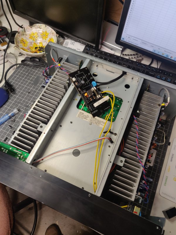
When the gremlin finally emerged, it was in the form of a mechanical rattling sound, almost certainly a relay flutter. Which relay, since there are three in the unit? The symptom continued when I turned off both sets of outputs, so it had to be the protection relay.
Hard to tell from the service manual, but it's found under the bottom cover.
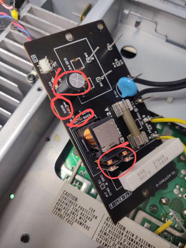
If a relay is staying closed but not maintaining continuity through the switch contacts, it makes sense to replace it or maybe you can get away with cleaning the contacts. But if it isn't staying closed, the relay is not usually at fault. When I repaired televisions in a previous career, it was de rigueur to find and replace a driver transistor and flyback diode (in this case TR102 and D205), because it often worked and because the parts were cheap and almost always on hand: you just needed a general purpose NPN transistor and rectifier diode. I replaced those, and C205 at the same time just because it was a 30+ year old electrolytic. None of the parts measured bad, but with an intermittent symptom you don't always expect that anyway. Looked for bad solder around the relay coil legs, didn't find any, but resoldered there anyway.
The symptom was now improved but didn't quite go away. Instead of rapid fluttering, you'd just get random isolated clicks every few minutes. So I included some 5v zener diodes in my next Mouser order, and when D206 got replaced, the symptom went away entirely. I suspect D206 and C205 were responsible together.
So much for the repair. Before talking about the recap, it should be mentioned that whenever the bottom cover is removed from this model, you're at risk of breaking front panel switches. The service manual warns about it. Never allow the front panel to bear the weight of the amplifier. Even when working on the main amp boards, which are accessible by removing just the top cover, you still need to do some stuff from the bottom because there are screwed-in ground connections and wire guides down there. So I used a nice thick book to keep the switches safe.
I found just one cap that was bulging, C589 in the left channel.
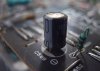
Denon uses quite a few electrolytics in this amp,
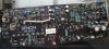
but most are small, and a recap wasn't going to break the bank. I did leave alone the big power filters in the center of the unit. Where possible I used audio grade replacements: Nichicon UFG for the 71v and 15v rail filters, Silmic II for most small value caps in and around the signal path. In a few locations calling for a low value / high voltage combination, I just made sure to use 105C rated caps instead of 85C.
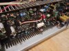
Just one minor spec change was involved. C558 was originally a 1uf 100v electrolytic responsible for locally smoothing the power rails for both IC502 and IC504, which are involved in the DC servo and bias circuits respectively. That seemed a little meager to me. The schematic shows 30v across it, so 100v is overkill. I replaced it with a 4.7uf 63v WIMA film cap (marked with white arrow in picture below), bypassed on the back side with a 0.1uf ceramic, added a 0.1uf ceramic across pins 4-8 of IC502 and yet another across the same pins of IC504. (This all refers to the right channel - for the left channel the locations are C557, IC501, IC503.)
After this I set the bias as indicated in the service manual and buttoned it up.
The recap makes it sound like an entirely new amplifier. Initially it seemed to be a little on the warm side, then after a few hours the high frequencies started to assert their proper place -- just with any previous tizzies tamed. You know how breakin is: it's hard to know how much is to be attributed to physical changes in the unit, especially with electrolytic caps involved, and how much is just your own head recalibrating to the music. In the end, I'm very pleased and enjoying a bit of a sonic honeymoon with it. I've been testing it first with my small-speaker system (Definitive Tech Celsius) and about to move it to the system with the Boston A150s. Nothing in this house is dying for 220wpc, to be fair!
I acquired a POA2200 power amp last year. The previous owner gave full disclosure that it seemed to have intermittent problems, but I couldn't make it misbehave. Actually the original arrangement was that I was going to repair it for him, but after weeks of No Problem Observed I offered to buy it - he'd already replaced it in his system - and we arranged a suitable bargain price.
When the gremlin finally emerged, it was in the form of a mechanical rattling sound, almost certainly a relay flutter. Which relay, since there are three in the unit? The symptom continued when I turned off both sets of outputs, so it had to be the protection relay.
Hard to tell from the service manual, but it's found under the bottom cover.
If a relay is staying closed but not maintaining continuity through the switch contacts, it makes sense to replace it or maybe you can get away with cleaning the contacts. But if it isn't staying closed, the relay is not usually at fault. When I repaired televisions in a previous career, it was de rigueur to find and replace a driver transistor and flyback diode (in this case TR102 and D205), because it often worked and because the parts were cheap and almost always on hand: you just needed a general purpose NPN transistor and rectifier diode. I replaced those, and C205 at the same time just because it was a 30+ year old electrolytic. None of the parts measured bad, but with an intermittent symptom you don't always expect that anyway. Looked for bad solder around the relay coil legs, didn't find any, but resoldered there anyway.
The symptom was now improved but didn't quite go away. Instead of rapid fluttering, you'd just get random isolated clicks every few minutes. So I included some 5v zener diodes in my next Mouser order, and when D206 got replaced, the symptom went away entirely. I suspect D206 and C205 were responsible together.
So much for the repair. Before talking about the recap, it should be mentioned that whenever the bottom cover is removed from this model, you're at risk of breaking front panel switches. The service manual warns about it. Never allow the front panel to bear the weight of the amplifier. Even when working on the main amp boards, which are accessible by removing just the top cover, you still need to do some stuff from the bottom because there are screwed-in ground connections and wire guides down there. So I used a nice thick book to keep the switches safe.
I found just one cap that was bulging, C589 in the left channel.
Denon uses quite a few electrolytics in this amp,
but most are small, and a recap wasn't going to break the bank. I did leave alone the big power filters in the center of the unit. Where possible I used audio grade replacements: Nichicon UFG for the 71v and 15v rail filters, Silmic II for most small value caps in and around the signal path. In a few locations calling for a low value / high voltage combination, I just made sure to use 105C rated caps instead of 85C.
Just one minor spec change was involved. C558 was originally a 1uf 100v electrolytic responsible for locally smoothing the power rails for both IC502 and IC504, which are involved in the DC servo and bias circuits respectively. That seemed a little meager to me. The schematic shows 30v across it, so 100v is overkill. I replaced it with a 4.7uf 63v WIMA film cap (marked with white arrow in picture below), bypassed on the back side with a 0.1uf ceramic, added a 0.1uf ceramic across pins 4-8 of IC502 and yet another across the same pins of IC504. (This all refers to the right channel - for the left channel the locations are C557, IC501, IC503.)
After this I set the bias as indicated in the service manual and buttoned it up.
The recap makes it sound like an entirely new amplifier. Initially it seemed to be a little on the warm side, then after a few hours the high frequencies started to assert their proper place -- just with any previous tizzies tamed. You know how breakin is: it's hard to know how much is to be attributed to physical changes in the unit, especially with electrolytic caps involved, and how much is just your own head recalibrating to the music. In the end, I'm very pleased and enjoying a bit of a sonic honeymoon with it. I've been testing it first with my small-speaker system (Definitive Tech Celsius) and about to move it to the system with the Boston A150s. Nothing in this house is dying for 220wpc, to be fair!
Last edited:


 .
. So I guess you ended up installing a single 4.7ohm 10 watt, like it probably had when new?