There is a previous thread that has a few of the differences between these tables, but is light on details. As I've had several of each of the ST-5 through 8 series, and have answered a lot of questions on eBay and asked a few on AK, I thought to contribute a little information here. Will do this over a few posts to this thread, feedback is my primary reason for doing this, you likely know something I do not, so feel free to comment, correct, add, etc.
General:
On / off
General:
- As best as I can tell, the sequence is ST-7, ST-8, ST-6, ST-5. But, it could also be ST-7, ST-8 as one series, and ST-6, ST-5 as another. Anyone know any better?
- The ST-8 had the (generally) same chassis / side wall, top plates and back cover as the other models, but was black anodized aluminum rather than brushed satin aluminum.
- All used the same basic linear arm drive mechanism: carriage riding on a tracking wheel riding on a tracking roller, angle of wheel tunable for speed of tracking
On / off
- The ST-7s and ST-8s had a power switch under the front of the chassis, basic on and off.
- The ST-5s and ST-6s had a rockwer power switch on the top of the table.
- Papst GS 38-09 - German manufacture, Hall effect sensor for speed feedback-loop - dual speed motor, with potentiometer controlled gross speed on the motor board, and individual speed controls accessible from the top plate for 33 RPM and 45 RPM fine tuning. Speed was adjustable with visual feedback from a mirrored strobe that displayed an under-platter pattern to provide visual feedback to fine adjust. This motor has been reported to be subject to speed variations, possibly due to small variations in line voltage. The under-platter pattern was either a paper pattern glued to the platter, or later a platter with the shiny dot patterns etched into the aluminum with a black background. Typical dots move to the right, slow it down, to the left, speed it up, using the fine controls. Single diameter belt pulley, two speed motor.
- Unknown mfg single speed synchronous motor, sync'd to line frequency. Not strobe feedback or adjustments, assumed to be line-frequency perfect. Used a two diameter belt pulley on the motor, and a mechanical system to move the belt from one diameter to the other.
- There were four circular patterns under the platter for the ST-7s and ST-8s
- 33 RPM - 60 cycle mains
- 45 RPM - 60 cycle mains
- 33 RPM - 50 cycle mains
- 45 RPM - 50 cycle mains
- The strobe was a simple 120v neon bulb, which switched on and off at a frequency depending on mains frequency
- There was a mirror that reflected the strobe light off the white/shiny dots into the viewer's eyes. The parts shipped with the TT's had a black peel-off label that the owner was instructed to place over the near or far part of the mirror in order to provide only the appropriate mains frequency reflection. Very clever.
- As stated above, the ST-7s and ST-8s had a two speed motor. The speed selection control was powered via three under-lit touch sensitive switches. Each switch had two small round metal terminals that when both touched would trigger the 33, 45 or off speed control. These touch controls became less sensitive over time, and now often require licking your finger before they will detect a touch. A fairly large circuit board handled this, and the motor speed control.
- Also stated above, the ST-5s and ST-6s had a lever that manually forced the belt up or down on a dual diameter pulley, effecting the platter speed. No fine adjustments.
- The tonearms are interchangeable across models
- The ST-8 had a black knurled coupler, and the other models had a grooved silver one.
- There were two styles of head shells, one flat metal, the other corrugated sides - not sure if there was anything except a cosmetic difference.
- All models I've seen of the 5s and 7s have the Harman Kardon name on the left front side panel.
- Some of the ST-8's had the name on the right of the front side panel.
- Some of the ST-8's had a different side panel height, which was mounted on the chassis at a different height, and so the platters ended up at the same overall distance from the bottom of the feet
- The ST-7s had non-adjustable feet, silver, held onto the rubber isolators by a screw that fit into the feet.
- The ST-6s, ST-8s and ST5s had adjustable feet that friction-fit into the rubber isolators
- The ST-8's had a muting circuit, which was a simple straight-through relay delay triggered by a microswitch that was tripped when the cueing plate descended.
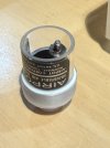
- The ST-5s, ST-6s and ST-7's had a slow needle-drop cueing mechanism used a DashPot - an automotive carburetor deceleration (well, negative acceleration) dampener (really, look up DashPot Ford). DashPot's are still available today, because, well, cars.
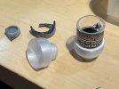
- The ST-8s used an AirPot, made by AirPot company, and still available, although very expensive, and you might have to wait until the make the next product run.
- If you have an ST-8 with an AirPot with a broken base (very common), I have 3D printed replacements, into which you can insert the glass sleeve, and seal.
- The carriage or the carriage tube rides on the slide rod, without lubrication and on Delrin bearings / bushings. On the ST-7, this rod was fixed (via set screws in each of the LH and RH support pillars), and HK determined that there was a very small amount of static (resting / non-moving) friction that could limit the smoothness of the linear travel. So they incorporated a belt / pulley system driven off the tracking shaft. This came in two flavors:
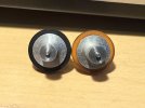
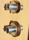
- The ST-5s and ST-6s had a groove cut into the right side of the tracking shaft as one pulley, and a plastic friction fit pulley on the slide rod, same right side.
- The ST-8s cut a groove in the tracking shaft pulley, moved the set screws, and used a shortened slide rod that only went between the center and the RH support pillars.
- The slide rod then rotates continuously, eliminating any moments of rest, eliminating the conditions of static friction and smoothing out the linear travel.
- A rotating slide rod is not necessary to the successful operation of the linear tracking, but it makes it better.
- The ST-8's end of record detection utilizes an LED, a photo-cell, and a simple circuit to detect the increased angle of the tonearm as it encounters the "fast" groove at the end (inner circle) of the record, moving the cartridge faster than the linear tracking.
- The ST-5s, ST-6's and ST-7s utilize a very sensitive mechanical lever that pushes the pin into the end-of-record gears and triggers the EOR process.
- The ST-7s used a ???? that rested on the guide rod to help keep the carriage in straight alignment
- The other models used a Delrin carriage guide that wrapped around the tracking roller and kept the carriage in straight alignment
- There were two types of roller covers, one all black "RABCO" lettering, and one with silver lettering
- This roller cover is critical to the accurate operation of the tracking / cueing. It spreads the 4 little springs, providing tension to the tone arm roller. This cover must be snapped into place to provide this tension. To do this, push down on the counterweight rod and the back of, and the tonearm at the front of, the carriage assembly (this spreads the tone arm roller slightly), and simultaneously snap the cover into place. Look at it closely first to proper align, it should snap in with only a small amount of spreading pressure.