Follow along with the video below to see how to install our site as a web app on your home screen.
Note: This feature may not be available in some browsers.
The move to the new server is done. There are some software and database maintenance updates in process. This has us passing the hat around to help out. We appreciate any donations. Seriously, even a dollar helps. The payment page may be found here - https://www.audiokarma.org/support.html
All four have new 20uF caps in the speaker crossover, and all four successfully produce ~1100VDC across C-2. So (knock on wood) my step-up transformers are OK.
While two work fine (s/n 6612 and 6637), one makes sound but is VERY quiet (6634); the fourth is totally dead (6462). I am worried that the panels themselves are going bad on 6634 and are already bad on 6462 ... but am not sure how to test the panels themselves. Well I guess I suppose I could swap panels around?
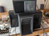
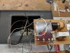
Here's a representative view of what they each look like inside. I've only replaced the selenium rectifier with diodes in 6612 and 6634; 6637 works fine w/ the original rectifier and even though 6462 makes no sound, it does make the ~1100VDC with the original rectifier.
Reading the patent ... col 4 lns 54-59: "The large electrostatic forces which result from the application of such a high electric field together with the large separation between electrodes make it possible to obtain high acoustic power output, per unit area over the entire range of audio-frequencies."
So it seems like, if my panels are getting the proper DC voltage, something is happening to prevent ionization between the front and back electrodes, thereby preventing electrostatic forces from creating physical translation of the membrane and thus the mute panels.
I looked at the audio step up transformers. They all measure continuous on the input side (although at the moment I have the 0.75 MH 6L-1 inductor wired (the thin wires wrapped around the capacitor) in place, so the continuity could come from that. I'll need to de-solder it to isolate the input side of the audio transformer.
However on the other side, nothing measures continuous, even in the good tweeter assemblies. There are three wires on the stepped-up side of the transformer, red, yellow, and orange. The schematic indicates that the red wire takes the audio signal to one electrode side, and looking at the wiring it's clear that the yellow takes it to the other side. So the orange is energizing the electrodes. But, none of them test continuous (red-yellow / red-orange / yellow-orange). I'm a bit stumped on this.



What about a certain mutual friend of ours, last time I checked he was going through speakers like a mad man, Vandersteen, JBL, Infinity ...