I have an MQ-101 that has some problems.
Symptoms:
Right channel is functioning properly.
Left channel has no bass boost. As far as I can tell it is passing the signal fine and the mid and hi controls are working. When the L bass control is adjust from or to setting one(flat) there is a slight thump in the left channel only. There is no boosting of the low frequencies at any of the settings.
What I have already checked:
It is not the interconnect cable and it does follow the channel when I swap things around so it is not the amp or the pre - it is defiantly the left channel on the 101.
I have cleaned the switches/controls on the 101 and verified them with a multimeter in the ohm setting including the 'input attenuator' switch on the rear of the unit.
I have checked the muting Relay (K1) on the power board and it seems to be working fine on both channels
I have noticed that (unlike the working channel) when I engage the bass boost on the left channel (any position except pos1)a reading of .07 VDC jumps to .36 VDC. This voltage change occurs at several locations in the circuit and does not happen in the working channel. I will include a picture of the schematic highlighted where this voltage rise occurs.
I have checked the voltages on the transistors on both boards. They are as follows: The odd # transistors on the top row are from the bad board (L). The even numbered transistors on the bottom row are their counterparts on the working board (R).
These readings were taken as described on the schematic. I did not notice any change when I engaged the L bass control above setting one 1.
I have also taken voltages from the power supply board and have attached a picture of the readings.
So what do you experts say?
Other questions:
There are two tantalum polarized electrolytic caps on each (L+R) board in this unit ( C7,8 and C29,30). Did they use tantalum for a good reason or should I replace with audio grade aluminum electrolytic caps ( one is in the signal path and one goes to ground)? I do plan on replacing the caps on the power board. I might keep the Mylar caps until I get the unit working properly and then decide if they need changing, or just change them while I am in there.
Any suggestions on best practices with maintenance/recap of this unit is appreciated. I am itching to hear my ML-1C speakers as designed for the first time!
Thanks!!

Symptoms:
Right channel is functioning properly.
Left channel has no bass boost. As far as I can tell it is passing the signal fine and the mid and hi controls are working. When the L bass control is adjust from or to setting one(flat) there is a slight thump in the left channel only. There is no boosting of the low frequencies at any of the settings.
What I have already checked:
It is not the interconnect cable and it does follow the channel when I swap things around so it is not the amp or the pre - it is defiantly the left channel on the 101.
I have cleaned the switches/controls on the 101 and verified them with a multimeter in the ohm setting including the 'input attenuator' switch on the rear of the unit.
I have checked the muting Relay (K1) on the power board and it seems to be working fine on both channels
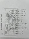
I have noticed that (unlike the working channel) when I engage the bass boost on the left channel (any position except pos1)a reading of .07 VDC jumps to .36 VDC. This voltage change occurs at several locations in the circuit and does not happen in the working channel. I will include a picture of the schematic highlighted where this voltage rise occurs.
I have checked the voltages on the transistors on both boards. They are as follows: The odd # transistors on the top row are from the bad board (L). The even numbered transistors on the bottom row are their counterparts on the working board (R).
| Q1 = 41.8V, 44.5V, 46.42V | Q3 = 75.5V, 46.49V, 45.86V | Q5 = 1.36V, 10.57V, 11.47V | Q7 = 9.78V, 1.36V, .80V | Q9 = 28.6V, .798V, .17V |
| Q2 = 41.8V, 44.3V, 46.19V | Q4 = 75.5V, 46.14V, 45.5V | Q6 = 1.36V, 10.57V, 11.47V | Q8 = 9.79V, 1.36V, .82V | Q10= 27.3V, .818V, .19V |
I have also taken voltages from the power supply board and have attached a picture of the readings.
So what do you experts say?
Other questions:
There are two tantalum polarized electrolytic caps on each (L+R) board in this unit ( C7,8 and C29,30). Did they use tantalum for a good reason or should I replace with audio grade aluminum electrolytic caps ( one is in the signal path and one goes to ground)? I do plan on replacing the caps on the power board. I might keep the Mylar caps until I get the unit working properly and then decide if they need changing, or just change them while I am in there.
Any suggestions on best practices with maintenance/recap of this unit is appreciated. I am itching to hear my ML-1C speakers as designed for the first time!
Thanks!!