• The move to the new server is done. There are some software and database maintenance updates in process. This has us passing the hat around to help out. We appreciate any donations. Seriously, even a dollar helps. The payment page may be found here - https://www.audiokarma.org/support.html

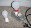
Dim bulb tester...

The problem here isn't the circuit, or the complexity of the design. It's a very simple thing to build.

The problem is that knowing how duplex wall outlets work and how to wire up combo switch/outlets has nothing to do with "electronics", and everything to do with wiring houses.

And when it comes to wiring houses we're all equally ignorant. My best suggestion is to replace that combo outlet with a ceramic lightbulb socket and a plain switch. It'll work perfectly the first time you wire it up.:yes:
 
The wiring is correct. However, are you testing the output with a bulb in place? I know it sounds obvious, but I'm just checking. Also, I believe there is a jumper built in so that ties the outlet feed to the switch feed. Just some food for thought.
 
Well if it were parallel wired you would still have a good way to test if something failed by the bulb going dim or completely going dark while popping a circuit breaker in the other room :p
j/k

Last time I had to test something this way I used my waffle iron as the "bulb" lol. Hey it worked and if anything were to go wrong what's the worse that could happen? Breakfast?

In all seriousness though I need to build a dim bulb tester. I am tired of plugging in half of a plug on each side of the rail of an extension cord and then wiring a piece of wire between the exposed prongs of both plugs. Besides it's not only a quick dirty way to test, but also slightly dangerous I suppose.
 
The wiring is correct. However, are you testing the output with a bulb in place? I know it sounds obvious, but I'm just checking. Also, I believe there is a jumper built in so that ties the outlet feed to the switch feed. Just some food for thought.

Took a chill pill. I have a feeling that this can't be wired correctly. Was I supposed to break the tab on the feed side? Looking at the image below, I had a black wire and white wire connected to one of each of the screws. They are connected. That's the job of the copper tab that the arrow is pointing to. It's also removable.


coppertab.jpg
 
The wiring is correct. However, are you testing the output with a bulb in place? I know it sounds obvious, but I'm just checking. Also, I believe there is a jumper built in so that ties the outlet feed to the switch feed. Just some food for thought.

I did have a bulb in place, yes.
 
Ok, I'll try to lead you through this. The easiest way to visualize this is that every device is in a series. The simplest way to accomplish this is to forget about the neutral wire and concentrate on the power lead (black). Now, we can't have a neutral and power hooked up to the same side of a receptacle so immediately take off that neutral that is wired to the brass side of the receptacle. The neutral wire (white) from your AC supply cable will be hooked up to the silver screw side of the receptacle and no other place.

You should wire the AC supply (black) line wire to the switch on one pole. Attach another black wire to the other pole. The added (black) line wire will terminate at one pole of the lamp fixture. From the remaining pole of the lamp fixture, attach a (black) wire and terminate this to one of the brass screws on the receptacle.

You can seee from the instructions above that the circuit is in series through the (black) line side of the AC to all of the devices. The circuit will not conduct from the line to neutral until a device is plugged into the receptacle to complete the circuit. The bulb is in the middle of this series circuit and serves to "use" some of the current before the receptacle and the powered device.

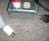
Below are some pictures (note the neutral wire side of the receptacle pictured has only one side of the duplex receptacle connected. This is to insure that no one uses it if the bulb tester is in use)

IMG_0001-15.jpg


IMG_0007-4.jpg


IMG_0006-3.jpg


IMG_0005-6.jpg


IMG_0002-8.jpg
 
My best suggestion is to replace that combo outlet with a ceramic lightbulb socket and a plain switch. It'll work perfectly the first time you wire it up.:yes:

I think you mean "replace that combo outlet with a ceramic lightbulb socket and a single receptacle"?
The switch is optional (and is the source of the problem here, I think...). You have to have a receptacle to plug the amp (or circuit being tested) into.....

I don't know how that switch is wired with the receptacle, and what the 4 screw terminals are for, but when I had a look online, I found some info here that confirms what fisherdude has been saying about removing that tab.

My version is a bit more primitive, but it works and was pretty simpleminded to wire up. Note- if you are using a duplex receptacle, both tabs need to be removed and the receptacles wired in series. The light bulb adapter goes in one receptacle, the test amp into the other. If you have a couple of lamp adapters, you can have different wattage bulbs to vary the max current allowed. (Lower wattage bulbs allow less current...)

Tom Bavis has the 'brightest' idea though....the fuse/bulb holder is in series with the outlet already.....easy wiring job.
 

Attachments

  • bulb limiter 1.jpg
    bulb limiter 1.jpg
    37.2 KB · Views: 26
  • bulb limiter 2.jpg
    bulb limiter 2.jpg
    59.8 KB · Views: 20
Below are some pictures (note the neutral wire side of the receptacle pictured has only one side of the duplex receptacle connected. This is to insure that no one uses it if the bulb tester is in use)

It looks to me like both receptacles are wired in parallel. Not a safety problem- perhaps you could just add a label: "Use either receptacle for testing."
 

Attachments

  • receptacle.jpg
    receptacle.jpg
    42.8 KB · Views: 19
As mentioned before, it's wired correct. Yes that tab needs to be removed. With that tab in place, you're basically bypassing the bulb.

When wiring in series this way, don't pay attention to wire colors. The white wire comming from the socket isn't a neutral, and thats why you're getting 0V from the 2 terminals on that side.

If you still can't get it to work, pm me and i'll walk you through it. I've been a residential/commercial electrician going on 10yrs now.
 
When wiring in series this way, don't pay attention to wire colors. The white wire coming from the socket isn't a neutral, and that's why you're getting 0V from the 2 terminals on that side.
Good point.
That's why I have the tape around the bulb base- the exposed base is electrically 'hot' and can give you a 'quick reminder' if you touch it accidentally.
 
A couple of pictures:
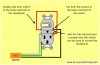
One is from the web showing how to wire the switch to control the receptacle.

I've done a clumsy re-draw to show the bulb added in series with the receptacle, which I think is what you want.

Again, check with a meter to make sure your switch is acting the same as the one in the pic.
 

Attachments

  • switchedoutlet.jpg
    switchedoutlet.jpg
    103.8 KB · Views: 143
  • switchedoutlet rewired.jpg
    switchedoutlet rewired.jpg
    91.7 KB · Views: 49
A couple of pictures:
One is from the web showing how to wire the switch to control the receptacle.

I've done a clumsy re-draw to show the bulb added in series with the receptacle, which I think is what you want.

Again, check with a meter to make sure your switch is acting the same as the one in the pic.

I'm going to try this tonight. The drawing on the right is what I've been trying to visualize. We'll see if it works. I've read over all the posts in this thread again. Will post results.
 
See the attachment for a simple wiring diagram. Done this way, your dim-bulb tester will work properly. I strongly suggest hooking up the safety ground to the metal box that you have it in, as well as to the outlet.

To test this--connect a working device to one of the outlets, install a sufficiently large light bulb in the socket, plug the tester in and turn the switch on. Provided the lightbulb is big enough, it may glow somewhat brightly while the device's filter capacitors charge and then it should settle down as the device starts operating normally.

Even though there is a white wire coming off of your light socket, treat it like a black wire. Color it black if that helps you visualize it.

This is the way I had wired up the one I made and it worked perfectly. Kortex, Have a look at this wiring diagram, post #13 on this thread. After you wire it up, it will show 120v on your meter, until you put a load on it.
 
Back
Top Bottom