• The move to the new server is done. There are some software and database maintenance updates in process. This has us passing the hat around to help out. We appreciate any donations. Seriously, even a dollar helps. The payment page may be found here - https://www.audiokarma.org/support.html

Diode Identification for JVC JA-S55

Corktowner

Active Member
Hello All. I need some help from the more experienced among you in order to identify a broken diode that I found while working on a JVC integrated. The diode is D603 and is only marked in the service manual with a JVC part number and a manufacturer. Google had nothing to say about either one of those, unfortunately.

The diode is located between a transistor and ground in what I believe is the power supply for the phono section. Not being an electrical tech or engineer, I am not sure how to judge from the circuit diagram what type of diode this should be, and the diode itself was broken in half (I believe ultimately a victim of the glue holding the 470 uF power caps).

As always, any direction will be greatly appreciated. I did search for “diode identification”, but the results all seemed very specific to their individual units, and not general instructions in circuit layout identification.

95544671-4407-4FA7-B10E-BD87E61AAA43.jpeg
 
Register to hide this ad
Hello All. I need some help from the more experienced among you in order to identify a broken diode that I found while working on a JVC integrated. The diode is D603 and is only marked in the service manual with a JVC part number and a manufacturer. Google had nothing to say about either one of those, unfortunately.

The diode is located between a transistor and ground in what I believe is the power supply for the phone section. Not being an electrical tech or engineer I am not sure how to judge from the circuit diagram what type of diode this should be, and the diode itself was broken in half (I believe ultimately a victim of the glue holding the 470 uF power caps).

As always, any direction will be greatly appreciated. I did search for “diode identification”, but the results all seemed very specific to their individual units, and not as much as a circuit layout identification.

View attachment 2025285
Reach out to Tom B. He’s repaired a bunch of JVC gear, several of my pieces and another AKers. He’s excellent.
Glenn
 
Reach out to Tom B. He’s repaired a bunch of JVC gear, several of my pieces and another AKers. He’s excellent.
Glenn

Its a 13.2v zener diode, and can be replaced by any 1n4743a (13v zener). Don't worry about the 0.2v difference as the tolerance is usually 20%. I suggest you get on ebay as there are a few us companies that sell them for under $3 for 10 and free shipping. Just make sure there arent any burnt resistors and make sure the X601, X603 transistors are OK, as well as the X602, and X604 transistors.
Good luck
 
Last edited:
Its a 13.2v zener diode, and can be replaced by any 1n4743a (13v zener). Don't worry about the 0.2v difference as the tolerance is usually 20%. I suggest you get on ebay as there are a few us companies that sell them for under $3 for 10 and free shipping. Just make sure there arent any burnt resistors and make sure the X601, X603 transistors are OK, as well as the X602, and X604 transistors.
Good luck

Tom and @Music2Myear , thank you very much. I will get the replacement Zener and go from there.

On a higher level, I did some research about what D603 does in the circuit. If I’m correct it is maintaining (Or limiting) 13.2V at the emitter of X603. As far as I can determine, this part of the circuit is acting as the regulated power supply for the class B amplifier stage. But as for why 13.2, that’s beyond me. If anyone can offer a lesson, all the better, but I have what I need now to keep this repair going.
 
Yes, the circuit posted are the + and - regulated power supplies. The Zener is the reference for the + regulator and since it's a tracking regulator the negative regulator gets it's reference form the output of the + regulator. The negative regulator will "track" the positive regulator by way of R609 and R611. Probably just a standard value in the Japanese Zener lineup.

Craig
 
Hello All. I need some help from the more experienced among you in order to identify a broken diode that I found while working on a JVC integrated. The diode is D603 and is only marked in the service manual with a JVC part number and a manufacturer. Google had nothing to say about either one of those, unfortunately.

The diode is located between a transistor and ground in what I believe is the power supply for the phono section. Not being an electrical tech or engineer, I am not sure how to judge from the circuit diagram what type of diode this should be, and the diode itself was broken in half (I believe ultimately a victim of the glue holding the 470 uF power caps).

As always, any direction will be greatly appreciated. I did search for “diode identification”, but the results all seemed very specific to their individual units, and not general instructions in circuit layout identification.

View attachment 2025285
The 13.2v right there in the schematic tells me it is a 13v Zener. And more than likely a 1/2 watt (500mW). As already mentioned by @Tom B , the 1N4743a will do the job.
 
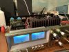
Hey Team JVC. I picked up the diode at the local electronics shop near Detroit (Shout out to Abel Electronics); they had them in stock for 2/$1. I replaced the diode and both STKs for $40 delivered from B+D Enterprises, then did a full recap, set the DC offset and main center voltage and we’re back in business! Special thanks to @Tom B and @Music2Myear for the diode info, Glenn @GD70 for being the JVC touchpoint, and @llwhtt for getting me through the previous JA-S55 rebuild - the experience made this one pretty easy.

78D0A621-4821-4645-9037-EEC99B5D8D57.jpeg
 
Last edited:
Back
Top Bottom