• The move to the new server is done. There are some software and database maintenance updates in process. This has us passing the hat around to help out. We appreciate any donations. Seriously, even a dollar helps. The payment page may be found here - https://www.audiokarma.org/support.html

DIY panel for testing amps (DBT+Variac+Ammeter etc.)

AlexHempel

AK Subscriber
Subscriber
In the past, I've always configured my amplifier test rig using alligator clips, but I figured I should create a hardwired setup. I want to be able to switch the DBT and variac in and out as necessary; when they are bypassed, they should be fully deenergized and entirely removed from the circuit. I also want to have a bypass switch for the panel ammeter in case the anticipated current draw exceeds its limits. The input will have a fuse holder to prevent excessive current in case of a short with the DBT switched out. I think I will use a G9.5 lamp holder instead of a normal E26 socket because I've discovered that very high wattage incandescent lamps (300w+) can be had for cheap in G9.5 form. Also, the G9.5 bulbs are far smaller than equivalent wattage E26. I have a few amps in my backlog that love current, so large wattages are necessary for the DBT to be useful.

I drew up a quick schematic in MS Paint and would appreciate any feedback on this circuit or the project overall. Once I've gotten started, I'll post some pictures. The panel ammeter, panel voltmeter, and variac are already en route. I plan on using an MDF panel for ease of drilling cutouts with the holesaw.

When choosing parts from Mouser, I realized that a 15 amp 120v 4PDT switch is somewhat exotic (and costs about $40), so I might replace that with two more DPDT.
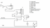
VariacDBTSetup.png
 
Register to hide this ad
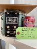
Variac has arrived. At 15 amps it's quite overkill, but I couldn't resist a NOS 1500B for the price I ended up getting. It's clearly never been used, as the fiber-board shipping collar is still in place and the windings have quite a bit of copper corrosion. Will have to open it up and deal with that.

image0.jpeg
 
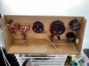
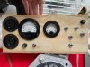
Update: only the wiring left! My woodworking is very amateurish -- it's plywood cut with a jigsaw. Holes drilled with a holesaw and widened with a dremel sander. Finish is water-based satin poly.

I ended up using two lamp holders -- one standard E26 and the G9.5 Halogen receptacle. Added two SPST switches to control them. Also working on the variac -- have cleaned off the severe corrosion on the exposed part of the windings using a pipe cleaner brush and contact cleaner. I'm running the wiper over the windings repeatedly to build up a bit of a graphite coating and prevent further corrosion.

image2 (6).jpeg

image1 (7).jpeg

image0 (14).jpeg
 
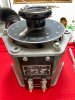
The variac is huge! I planned to panel mount it, but there's no way this plywood could withstand the weight without bending, and it would take up a lot of space on my table. It's going on a nearby shelf and I'm gonna connect it with some sort of cable. Not exactly sure how yet -- I'll start with some jumpers and find a better solution later.
 
The variac is huge! I planned to panel mount it, but there's no way this plywood could withstand the weight without bending, and it would take up a lot of space on my table. It's going on a nearby shelf and I'm gonna connect it with some sort of cable. Not exactly sure how yet -- I'll start with some jumpers and find a better solution later.
put it somewhere drop-proof, that thing can/will f*%k shiite up if it gets inadvertently pulled or knocked off whatever it's parked on.
 
Very good idea !

Btw, you can bypass the bulb and/or the Ammeter with one switch across them, jumping the device. You don't need an inverter to do those bypass.
 
@AlexHempel Let me tell you, what you're doing is excellent. My problem (well, at least one of them...) is if I put something quick and dirty together I will almost never get around to building something better. Good on you for actually doing it!
 
Very good idea !

Btw, you can bypass the bulb and/or the Ammeter with one switch across them, jumping the device. You don't need an inverter to do those bypass.

The reason I was using a DPDT is so they could be completely deenergized when bypassed. Is there any way to achieve this with a single pole switch? In retrospect, there's no real reason to do this for the ammeter. Not sure what my concern was, but I already bought the switch.
 
Those Adjust a Volt variacs are great . Have one in each of my test benches at work 20A bench and 40 Amp bench. 0-260VAC, 400-600VAC thru a 2X transformer @10A. 60-400Hz. Tested temperature controllers 4A-30A units. Really nice setup you have going. Been doing this since 82. Using fast-ons get a good crimp done. Bad connections lead to overheated connections quick . Like the "teflon" coated wire better than some of the cheaper types. A lot harder to damage the insulation in use 12-14 ga wire.
 
The reason I was using a DPDT is so they could be completely deenergized when bypassed. Is there any way to achieve this with a single pole switch? In retrospect, there's no real reason to do this for the ammeter. Not sure what my concern was, but I already bought the switch.
I see. if you want the bulb completely deenergized, you need to disconnect it from both ends. My DBT bypass just jumps the bulb contacts with single pole switch.
 
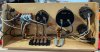
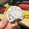
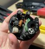
Alright, I've got everything wired up. Unfortunately, I somehow forgot to test my panel voltmeter, which appears to be dead (broken connection somewhere I think). Going to see if I can open it up and fix it. Everything else appears to be working fine.

PanelMeterBack.jpeg
 
Back
Top Bottom