• Please note that Audiokarma will be offline briefly for updates early on Monday morning, September 28th.

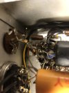
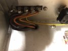
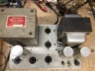
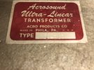
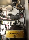
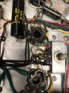
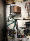
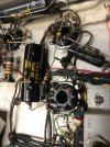
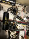
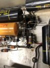
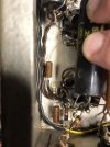
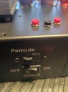
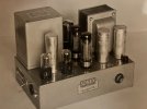
Does anyone have any info on this (Acrosound?) amplifier?

Sam Lysinger

Please support your local mad scientist
Subscriber
I rolled the dice on this amplifier and the iron tests good. (Well, the bias transformer seems to have a shorted winding so it was only putting on -21v DC...)

Radiomuseum has this listing: https://www.radiomuseum.org/r/acrosound_ultra_linear.html

And that's all I can find. Was it a kit like the Ultralinear-II? Does someone have an official schematic or manual squirreled away. No worries if not as I suspect it uses the high power Williamson circuit from the transformer catalog based on the resistor values and a filament transformer being used as a bias supply.

All insights are greatly appreciated.

PS: The TO-360 OPT measured a couple hundred more ohms per winding than a TO-600 (and does not have a dedicated NFB winding)
4969.228313​
16​
4435.929851​
8​
4946.262529​
4​
 

Attachments

  • IMG_5898.JPG
    IMG_5898.JPG
    128.6 KB · Views: 110
  • IMG_5903.JPG
    IMG_5903.JPG
    113.5 KB · Views: 105
  • IMG_5902.JPG
    IMG_5902.JPG
    88.3 KB · Views: 93
  • IMG_5901.JPG
    IMG_5901.JPG
    61.4 KB · Views: 100
  • IMG_5900.JPG
    IMG_5900.JPG
    148.5 KB · Views: 104
  • IMG_5899.JPG
    IMG_5899.JPG
    81.8 KB · Views: 111
Register to hide this ad
Ha ha ! :)

Well, it looks like an homebrew amplifier, very well made, or a prototype for the Eico HF60, or another brand.
Acrosound was selling their OT so all, so this could be from any source.

The TO600 is a special beast, and as you stated has a feedback winding.

I have a pair of TO350 but not TO360. Unknown to me.

From the picture I could not make if it is a fixed bias type like the Eico HF60 as it seems like, or a Williamson. A picture of the whole inside would help.

But definitely a high power amplifier, and with Acrosound Iron, this will rocks. Good catch ! :)

I hope it helps,
Brice.
 
Ha ha ! :)

Well, it looks like an homebrew amplifier, very well made, or a prototype for the Eico HF60, or another brand.
Acrosound was selling their OT so all, so this could be from any source.

The TO600 is a special beast, and as you stated has a feedback winding.

I have a pair of TO350 but not TO360. Unknown to me.

From the picture I could not make if it is a fixed bias type like the Eico HF60 as it seems like, or a Williamson. A picture of the whole inside would help.

But definitely a high power amplifier, and with Acrosound Iron, this will rocks. Good catch ! :)

I hope it helps,
Brice.
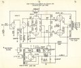
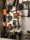
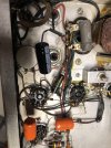
It is fixed bias and, I believe, also a Williamson. Here are more pics and a copy of a schematic that it looks very much like.
 

Attachments

  • IMG_5911.JPG
    IMG_5911.JPG
    125.3 KB · Views: 71
  • IMG_5910.JPG
    IMG_5910.JPG
    164.3 KB · Views: 40
  • IMG_5909.JPG
    IMG_5909.JPG
    132.1 KB · Views: 39
  • IMG_5908.JPG
    IMG_5908.JPG
    141.9 KB · Views: 40
  • IMG_5907.JPG
    IMG_5907.JPG
    148.2 KB · Views: 39
  • IMG_5906.JPG
    IMG_5906.JPG
    119.5 KB · Views: 41
  • IMG_5905.JPG
    IMG_5905.JPG
    96.5 KB · Views: 72
  • highpowerwilliamson.JPG
    highpowerwilliamson.JPG
    110.8 KB · Views: 75
Looks like a bit of a mish-mash (are those two .05uF coupling caps?) of Williamson designs, but basically, yeah, looks like the Keroes/Hafler high-powered Williamson.

Tim's snark refers, I believe, to the somewhat hazardous fixed-bias design, which puts a significant amount of positive voltage on the output tube grids, which is then countered by a larger-than-normal negative bias voltage. If the bias supply fails, the grids go positive and a meltdown is pretty much guaranteed. The purpose of the coupling-cap/resistor combo was to improve low-frequency stability, but it's a little dicey. I built a pair but abandoned them for my bog-standard 22 watt cathode-bias Williamsons. AK member trainbuffton just restored a pair that used the Dynaco A-430s and likes them very much.

There were no official kits that I know of, and it's not often that you see them compared to the lower-powered homebrew Williamsons, but they seem to be turning up more frequently these days.
 
Last edited:
More of a snivet than a snark :cool:

It's certainly one method to suppress low frequency phase change in the region where output transformer phase changes abruptly around its resonance. Although, I've become a fan of Dave's method of significantly increasing the value of the earlier cap - it avoids the dc bias hassle, and afaik has no disadvantages, although I'm sure there could be some consequences wrt dc bias changes.
 
I think from other discussions about an amp I have that uses a similar cap bypassed with resistor that it has something to do with LF stability. I suspect you may be able to get the same job done by losing the bypass resistor and making those caps a fair bit larger. Not doing any math but the first 0.25 working into a 470k load will have a turnover point 4.7x lower than an 0.25 into a 100k load. Probably want that more like 10x, so if you double the value of the second cap and dump the 1M it may very well get you there.

bias circuit voltages will need some tweaking but thats easy.
 
With the two coupling caps, and an output transformer with a peaky LF resonance, the phase change at that resonance can very rapidly rise towards 180 deg over a few Hz (often in the 5-10Hz range in the Williamson's I've tested. Removing or avoiding the effects of one of those coupling caps makes the phase change more sedate around the resonance and delays the rise to 180deg down to often below 1Hz.

One plausible advantage of keeping the coupling cap to the output stage at a low value is that the grid current of the output stage has less effect in causing and recovering from dc voltage shift across the coupling cap (as per blocking distortion if the output stage approaches or reaches Vgs=0V).
 
some of it also may have been component availability. High voltage 1 microfarad paper or film caps in the late 50s were uncommon and quite large.
 
Hey Sam... your noble asst. here!
There is a 1950's hifi brand called Sonex that used similar labeling on their chassis. They are hard to find, and the only one I've seen had a Dynaco potted OPT (it was sold by Chong on eBay several years back).
Would suggest some nice Vitamin Q .22's for coupling cap replacement! The yellow label Spragues are oil filled and will be bad most likely, unlike the later mylar red label "Black Beauties."
 
Hey Sam... your noble asst. here!
There is a 1950's hifi brand called Sonex that used similar labeling on their chassis. They are hard to find, and the only one I've seen had a Dynaco potted OPT (it was sold by Chong on eBay several years back).
Would suggest some nice Vitamin Q .22's for coupling cap replacement! The yellow label Spragues are oil filled and will be bad most likely, unlike the later mylar red label "Black Beauties."
Panasonic earthtones are destined for this amplifier ^_^ Finally found my box of filament transformers so I can get the bias circuit rebuilt.
 
It's alive... It's alive! MUHAHAHAHA!

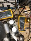
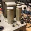
The Astron cap on the left was toast (with the rectifier tube installed, it was pulling almost 3 amps with no power tubes and it took 20 minutes for the metal can to cool off).
All the coupling caps were leaking more than 1ma each.
The bias circuit needs more voltage drop as the highest it goes to is -48v (which is why the 6550s are in it). I blame the selenium rectifier replacement for this.
The Gillespie mod 2.2uf caps are on order so you will note the distinct lack of clean soldering.
Interestingly, none of the resistors are out of spec. I truly dislike the bias pot on the bottom, but I may be able to stuff a balance pot in there somewhere or swap it for the hum balance pot to make life easier.

It sounds pretty darn good on the sacrificial test speaker.

I'll send another update when the next round of work gets done.
 

Attachments

  • IMG_5956.JPG
    IMG_5956.JPG
    128.7 KB · Views: 24
  • IMG_5955.JPG
    IMG_5955.JPG
    147.1 KB · Views: 24
  • IMG_5954.JPG
    IMG_5954.JPG
    149.2 KB · Views: 24
  • IMG_5952.JPG
    IMG_5952.JPG
    144.1 KB · Views: 23
  • IMG_5950.JPG
    IMG_5950.JPG
    151.7 KB · Views: 23
You can just drill a hole on the top of the chassis and relocate the bias pot.
Even add a couple bias test jacks.
I addedntest jacks to a tube guitar tube amp I built for my son.
I haven't added a bias pot on top yet, its still underneath.
But at least he can easily check the bias.
 

Attachments

  • 20240815_102210.jpg
    20240815_102210.jpg
    79.8 KB · Views: 9
i had my first modern cap fail about a week ago with one of those Panasonic caps. No idea what happened but it went leaky, shorted for a moment and went back leaky. No damage besides a fuse, and the one last of that type i had in the box works fine, so do the other 3. Guessing it was just a dud.
 
Sam was gracious enough to let me borrow this amp for some listening on my home system. So far, I am really enjoying it. It sounds like a more punchy and detailed/authoritative Dynaco Mark III. I would certainly say it has the upper edge on a typical Mark III. Another friend of mine was kind enough to share with me some old press photos and information from Sonex that was in his archives. Attached is a press photo of this amplifier from about 1955 or so. I do not have a schematic or anything- just this photo. Sonex made other amps, including a push pull parallel KT66 amp with an Acrosound TO-330 output transformer, as well as some other Williamson type amps with Dynaco potted output transformers. They apparently also made a preamp, but I have never seen one in person. The Sonex company (Sonex Inc.) was located at 245 Sansom St. Upper Darby, PA- which Google Maps shows as a house! Sonex was obviously a very small outfit- maybe even ran by only a couple employees.
The other Sonex literature that I have is all handtyped on a typewriter and is ditto machine copies and hand-drawn schematics. Fascinating.

While Sam is using 6550 in his amp (which it functions fine with), it is interesting to note the use of metal base EL34's. Measured plate voltage at 113v was 435v DC, so right at the edge of what EL34's can handle. The metal base ones were made by Amperex and usually could withstand being run right at design maximums without failing. (I have seen many original metal EL34's still running in Dynakit MKII... and the MKII instructions for the bias mention that a "dull red glow on the plates" is standard for operation at the Dynaset bias point!) Ha!
 

Attachments

  • Sonex Acrosound Press Photo.jpg
    Sonex Acrosound Press Photo.jpg
    82.9 KB · Views: 21
So what is the plate-to-plate load of this TO360? And at what percentage is its U-L tap located at? I assume this is a TO-330-ish beast, rather than the CFB-equipped TO-350, yes?

General curiosity...it is fo' sure unlikely that I will ever turn up a set...LOL
 
Back
Top Bottom