• The move to the new server is done. There are some software and database maintenance updates in process. This has us passing the hat around to help out. We appreciate any donations. Seriously, even a dollar helps. The payment page may be found here - https://www.audiokarma.org/support.html

Dummy Load Build- Input Welcome

kevin b

AK Subscriber
Subscriber
Hi all,
It's time to make a dummy load to allow for more thorough testing of the receivers that I've been learning to repair. The biggest one I have currently is 120 WPC, but you never know what will come along. I'm hoping that I might avoid any mistakes by learning from someone else's if possble.

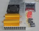
Below are some parts that I've started to gather. There will be four 200 watt 8 ohm resistors. The 80mm fan there is just a representative one for size comparison.
DL5.jpg

After watching some videos and reading about other builds, I decided on these features:
1) Ability to run the shop stereo through it
2) 4/8 ohm switchable resistance
3) X1/X10 switchable scope output

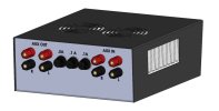
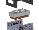
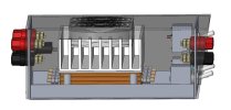
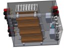
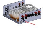
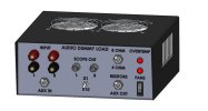
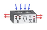
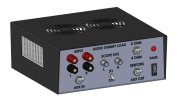
Here is what I think it will look like, although I'm open to suggestions.
DL1.jpg
DL2.jpg
DL3.jpg
DL4.jpg
DL4A.jpg
The idea is that I would run my shop (bench) stereo speakers through the back, and the input and output switches would be set to Aux when I'm not testing a bench amp.

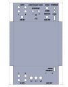
For the case bottom, I can cut out and engrave Aluminum sheet on my CNC Router, then bend up the flanges. The top would be steel, possibly laser cut and bent by Send-Cut-Send for a more professional look as shown. Alternately I could make it myself with round fan cutouts and wire guards.

I don't really expect it to be able to dissipate the full 200W per resistor, but wonder if anyone has an educated guess at about what it will be able to do. I don't want it to be very loud, so will try to use some quiet lower CFM fans to start. It seems like it would be pretty easy to find out what the full-time power handling capacity is after it's built.

One thing I've seen on others is a thermostat to run fans, or sound an alarm if the temperature gets too high. Both of those sound like good ideas, so I'm wondering if anyone thinks they are worthwhile or overkill. It seems like a low temperature snap switch to turn on the fans, and a higher temperature one for an alarm would be easy.

Fuses are kind of up in the air also. I think I saw one with 100mA fuses for the scope outputs. Another had 5A fuses on the inputs. Any recommendations here? The .5A shown would be for the fans.

I haven't made a schematic yet, as I am electrically challenged, but will do that after deciding on any extra safety features.

Suggestions or feedback of any kind are welcome!

Kevin
 
Register to hide this ad
Looking forward to this build !!!

Keep us posted.

I think you have everything covered.

I just made one to work with my Sound Technology ST 1200.

54423104468_f1cf43a59e_b.jpg


Nashou
 
Looks Good Nashou. I looked up that ST 1200, and I'm pretty sure I wouldn't know what to do with it.

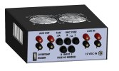
Anyway I decided to add some stuff. There is a thermal switch to turn the fans on at 40C and back off at 30C, assuming the FAN switch is on. There is also a thermal switch to turn an indicator light and buzzer at 80C, and back off at 60C. There will also be a switch on the back to silence the buzzer temporarily.

Dummy Load.jpg
Dummy Load2.jpg

Now I'm waiting for a couple parts to get here to confirm cutout sizes, and then this should be able to cut this out on the router.
Dummy Load3.jpg

Oops I just noticed that I need a 12V power input jack. I'll post more when there is progress.
 
Looks like a pretty good grasp of CAD.:thumbsup:
Thanks, it's a job necessity that's handy for personal stuff. I've kind of forgotten how to make anything without drawing it first though. Pink World is one of my favorites BTW only if i have time to listen to whole thing.

I think this will be it- maybe fuse overkill. The metal fan guards should give better airflow than cutouts anyway so I'll probably made the cover myself also.

Dummy Load5.jpg
Dummy Load6.jpg
 
It appears form follows function. Mine looks kinda similar to yours, but with fewer features, haha. I also went with selectable load resistances.

Just one thing to keep in mind; if you have any intention of using this unit with tube amplifiers, the fuses could become a real liability. Most tube amps, especially at high power output levels, will not survive the loss of their load. The usual result is the destruction of an output transformer, which are pricy at best, irreplaceable at worst.

DSCF2059.JPGDSCF2065.JPG
 
It appears form follows function. Mine looks kinda similar to yours, but with fewer features, haha. I also went with selectable load resistances.

Just one thing to keep in mind; if you have any intention of using this unit with tube amplifiers, the fuses could become a real liability. Most tube amps, especially at high power output levels, will not survive the loss of their load. The usual result is the destruction of an output transformer, which are pricy at best, irreplaceable at worst.
Thanks arts, I figured I'd wait to tackle tube amps for a while, but that's good to know. I could just put solid steel blanks in for fuses, for tube amps suppose. I remember seeing your dummy load when I was researching them, and liking that case .IIRC there are fans in the back, which is probably a better way to go.

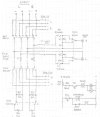
I made a schematic and wonder if anyone has any suggestions for changes or additions. It seems pretty simple but I don't know what I don't know.
Schematic.jpg
 
Nobody objected to the schematic, and I see thumbs up so I'll go with that. I'm not sure how much interest you electrical wizards have in mechanical/manufacturing types of things, but here are some progress pictures.

The case bottom was cut out of 16 gauge Aluminum on my home made CNC router with an 1/8" bit, then engraved with a .020" bit.

Router.jpg
Engraving.jpg

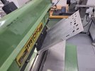
After that, the flanges were bent on my little combination sheetmetal machine.

Bending.jpg

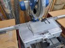
The heatsink was cut to size with a chop saw and table saw.

Heatsink.jpg

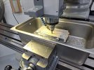
Next a 1/2" deep pocket was milled to set the fans in a little. Wood strips stabilized the fins during milling.

Milling.jpg

All of the parts are here, and there are just a few more mounting holes to add before it can be all put together and wired. It's funny how pictures show up things that I miss by eye. The letters were painted in, and I see that there is still a little paint to be sanded off. I'll spray a clear coat on it also before final assembly.

Parts.jpg

That's it for now, hopefully the next post will be after it's all wired and working.
 
Nobody objected to the schematic, and I see thumbs up so I'll go with that. I'm not sure how much interest you electrical wizards have in mechanical/manufacturing types of things, but here are some progress pictures.

The case bottom was cut out of 16 gauge Aluminum on my home made CNC router with an 1/8" bit, then engraved with a .020" bit.

View attachment 3653709
View attachment 3653710

After that, the flanges were bent on my little combination sheetmetal machine.

View attachment 3653711

The heatsink was cut to size with a chop saw and table saw.

View attachment 3653712

Next a 1/2" deep pocket was milled to set the fans in a little. Wood strips stabilized the fins during milling.

View attachment 3653713

All of the parts are here, and there are just a few more mounting holes to add before it can be all put together and wired. It's funny how pictures show up things that I miss by eye. The letters were painted in, and I see that there is still a little paint to be sanded off. I'll spray a clear coat on it also before final assembly.

View attachment 3653714

That's it for now, hopefully the next post will be after it's all wired and working.
Looks good. I would have brushed the face plate . I use a belt sander for that. Wish I had more know how, like you have , with the metal working gear!!

Athanasios
 
Looks good. I would have brushed the face plate . I use a belt sander for that. Wish I had more know how, like you have , with the metal working gear!!

Athanasios
Thanks, I have had good results with my edge sander getting deep scratches out of the tops of faceplates, but couldn't get a very uniform finish on a test piece for this. I probably need a finer grit belt. I think this will be ok for what it is though.

Looking at your build thread and others makes me wish I had more electronics and audio equipment knowledge in general. There's a lot learn, but so far it's been a fun challenge.
 
FWIW, you might wish to consider designing your fan cooling layout to force air into the dummy load instead of exhausting sustained elevated temperature heat through the fans, as they might not last as long as having cooler ambient air passing through them on the way to your load resistors.

Ever notice tower/desktop computer power supplies are configured that way, because the power supply carries all the computer`s power requirements loading through it.
High power forced air SS amplifiers of good cooling design configurations usually do the same.

Just an suggestive thought.
 
FWIW, you might wish to consider designing your fan cooling layout to force air into the dummy load instead of exhausting sustained elevated temperature heat through the fans, as they might not last as long as having cooler ambient air passing through them on the way to your load resistors.

Ever notice tower/desktop computer power supplies are configured that way, because the power supply carries all the computer`s power requirements loading through it.
High power forced air SS amplifiers of good cooling design configurations usually do the same.

Just an suggestive thought.
Thanks for that Bill. The fans draw air in from top and blow it out the sides, so it will work as you suggest.
Cooling.jpg


Air blows fairly hard out the sides, and feels comparable to the airflow out of a small 500 watt heater that I have, so it seems like it will be okay. I'll have to be careful about what's sitting next to it.

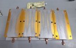
The bottoms of the resistors weren't very flat, so I lapped them a little on a surface plate for better contact and to minimize the amount of thermal compound necessary.
Flat.jpg
Resistors.jpg

Something that I neglected to model in was a way to mount the voltage divider resistors, and it also needed terminals to wire in the parts with fling leads (overtemp buzzer and indicator lights.) It took all of my pea-brain power to figure out where to fit this little board with those things, and also a header to plug the fans in, and another resistor to quiet down the obnoxious buzzer.

Board.jpg

The 4/8 ohm switch is used, and has already had wires soldered to it. The bottom switches are NOS from eBay though, and I found it impossible to get solder to stick to the terminals on those. I tried using flux and even filed down to the base metal, and could barely get solder to stick. It would take way too long to use them, so new switches with screw terminals are on the way.

During wiring, I realized that there were a couple of mistakes on the schematic that I'll show corrected when it's done. I also changed the fan light wiring to confirm that there is power when the switch is turned on, rather than having it light up only when the fans are running. I don't think it should have been in series with the fans as drawn anyway.

It's getting close; I'm just waiting for the switches, and better lights because the first ones I ordered seem like junk.
 
Last edited:
Thanks for that Bill. The fans draw air in from top and blow it out the sides, so it will work as you suggest.
View attachment 3655808


Air blows fairly hard out the sides, and feels comparable to the airflow out of a small 500 watt heater that I have, so it seems like it will be okay. I'll have to be careful about what's sitting next to it.

The bottoms of the resistors weren't very flat, so I lapped them a little on a surface plate for better contact and to minimize the amount of thermal compound necessary.
View attachment 3655824
View attachment 3655826

Something that I neglected to model in was a way to mount the voltage divider resistors, and it also needed terminals to wire in the parts with fling leads (overtemp buzzer and indicator lights.) It took all of my pea-brain power to figure out where to fit this little board with those things, and also a header to plug the fans in, and another resistor to quiet down the obnoxious buzzer.

View attachment 3655835

The 4/8 ohm switch is used, and has already had wires soldered to it. The bottom switches are NOS from eBay though, and I found it impossible to get solder to stick to the terminals on those. I tried using flux and even filed down to the base metal, and could barely get solder to stick. It would take way too long to use them, so new switches with screw terminals are on the way.

During wiring, I realized that there were a couple of mistakes on the schematic that I'll show corrected when it's done. I also changed the fan light wiring to confirm that there is power when the switch is turned on, rather than having it light up only when the fans are running. I don't think it should have been in series with the fans as drawn anyway.

It's getting close; I'm just waiting for the switches, and better lights because the first ones I ordered seem like junk.
FWIW, When I`ve encountered tarnished looking and possibly reluctant NOS switches solder terminals to accept solder, or really look like they might be problematic I try wiping them down with a few cotton swabs dipped in Tarn-X for a few minutes before spraying the solder connectors clean with contact cleaner, that usually works well.

Also I found out early on in the early eighties when modifying a 1975 purchased a brand new economical priced Heathkit brand dummy load (my first) to need to have much higher wattage resistors exchanged for the original (4) 50 watt 8 ohm ones to (4) 350 watt 8 ohm upgrades, due to the ever increasing wattage SS amps being brought to me, that sustained high power testing Will soften, or even melt the originally foolishly soldered connections used in the upgraded dummy load resistors connections (even with a 6" 120 v muffin fan blowing upwards from underneath wide open), so I used 12 ga, solid copper wire with uninsulated crimp ring connectors and SS securing hardware (nuts, bolts internal tooth lock washers) for all internal connections when I reworked it.

400, and above per channel RMS watts pumped into it for sustained periods of time can really heat up the fully all sides but the front panel perforated dummy load`s housing can generate a lot of concentrated heat in a short period of time while full unclipped power stress testing of PA amplifiers.
Haven`t had to mess with it since.
 
FWIW, When I`ve encountered tarnished looking and possibly reluctant NOS switches solder terminals to accept solder, or really look like they might be problematic I try wiping them down with a few cotton swabs dipped in Tarn-X for a few minutes before spraying the solder connectors clean with contact cleaner, that usually works well.

Also I found out early on in the early eighties when modifying a 1975 purchased a brand new economical priced Heathkit brand dummy load (my first) to need to have much higher wattage resistors exchanged for the original (4) 50 watt 8 ohm ones to (4) 350 watt 8 ohm upgrades, due to the ever increasing wattage SS amps being brought to me, that sustained high power testing Will soften, or even melt the originally foolishly soldered connections used in the upgraded dummy load resistors connections (even with a 6" 120 v muffin fan blowing upwards from underneath wide open), so I used 12 ga, solid copper wire with uninsulated crimp ring connectors and SS securing hardware (nuts, bolts internal tooth lock washers) for all internal connections when I reworked it.

400, and above per channel RMS watts pumped into it for sustained periods of time can really heat up the fully all sides but the front panel perforated dummy load`s housing can generate a lot of concentrated heat in a short period of time while full unclipped power stress testing of PA amplifiers.
Haven`t had to mess with it since.

Some good lessons there. I was planning on crimping the resistor ring terminals, but using non-insulated ones sounds like a good idea also. It's crazy how much unassembled Heathkits sell for on eBay these days. I wish I still had the little power supply that I built while learning to solder as a kid, probably around 1975. I wouldn't have known what to do with a dummy load back then.

I'm already wishing that I made it bigger, because there is a local guy who buys abandoned storage units with a nice looking Pioneer Spec 2 amp. He says that only one channel works, and is asking $600 for it. He has some other stuff I want, so I'll see if I can get it for a more reasonable price with a package deal. It would be a nice addition to my current Pioneer rack system.

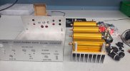
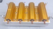
Anyway, I thought I would test what I can for now with the power supply pictured below, turned all the way up. It looks like the best I can get out of it is the equivalent of about 75 WPC unless there's more to it than DC Volts X Amps for audio power equivalency. The two outputs are connected to the middle two resistors. After a few minutes, the fans turned on, and after an hour there is reasonably warm air blowing out the sides. The heatsink is warm but not uncomfortable to touch, so I think it will be fine for testing the medium-power amps that I have. I'm not sure how long it would go with a 250WPC Spec 2 though...

First Test.jpg
 
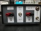
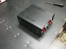
Well, I had to re-make the case a couple inches longer because it was too tight to add the rest of the wiring. It's all together now except for the cover, and everything seems to work as intended. I'll report back once more when I find out how much power it will take, or anything else that might be of interest.

20251231_105720[1].jpg
 
Back
Top Bottom