• The move to the new server is done. There are some software and database maintenance updates in process. This has us passing the hat around to help out. We appreciate any donations. Seriously, even a dollar helps. The payment page may be found here - https://www.audiokarma.org/support.html

Dummy Load Heatsink

hpmachining

New Member
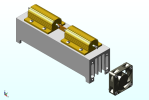
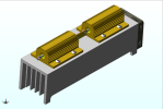
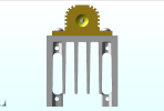
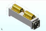
I have some leftover 2-1/4" square 6061 aluminum and thought it would be good to make a couple of heatsinks for dummy loads. How does my design look? According to my CAD, I have ~.125m^2 of total surface area. I plan on using these resistors and fans. I figure I can connect the 2 blocks in parallel to get (1) 400W 4Ω load for checking a subwoofer plate amp I'm working on.

NHS100 4R F - 100W 4Ω, 2 for each block
MF50151V1-1000U-A99 - 50x50x15mm 12V 17CFA, 1 for each block

CAD file posted on GrabCAD if anyone is interested in a closer look.
Heatsink for Dummy Load

This is the mass out report (just the heatsink) from my CAD system:
=======================================
Area 125224.05204466 mm^2
AWD 1.00000000 mg/mm^2
Surface Mass 125224.05204466 mg
Density 2.70000000 mg/mm^3
Volume 219595.19086805 mm^3
Mass 592907.01534374 mg
 

Attachments

  • Dummy_Load_Heatsink_1.png
    Dummy_Load_Heatsink_1.png
    186.6 KB · Views: 15
  • Dummy_Load_Heatsink_2.png
    Dummy_Load_Heatsink_2.png
    177.3 KB · Views: 17
  • Dummy_Load_Heatsink_3.png
    Dummy_Load_Heatsink_3.png
    175.4 KB · Views: 13
  • Dummy_Load_Heatsink_4.png
    Dummy_Load_Heatsink_4.png
    50.6 KB · Views: 17
Register to hide this ad
Looks good; fan makes a big difference in efficiency. Your description says square aluminum which I pictured as just square tubing but the CAD graphics show extruded with fins which of course provides much more surface area for faster heat transfer to ambient air.
You could always add a cheap digital thermometer to it if you wanted to monitor the temp precisely. Some of the digital multimeters (DMM) come with a thermocouple so you could just make a hole or bracket to attach and detach the probe as desired.
Nice Job!
 
Your description says square aluminum which I pictured as just square tubing but the CAD graphics show extruded with fins which of course provides much more surface area for faster heat transfer to ambient air.
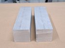
It is solid bar stock now. I need to machine the fins. I might get to that today. I'll post pictures when I'm done. Might as well post a "before" picture :)
Not CAD, not Abscence of Intelligence, not a cartoon:
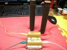
Not sure if that is a dig at my CAD work or not, but regardless, I like those (2) 300W resistors. Do they need to be cooled at all when you use them? I'm a bit of a newb at this and have not seen those before. I thought about just making blocks long enough to hold just one resistor, similar to your Arcol resistor setup, but opted for my current design. I'm probably overdoing it, but I do tend to do that.
 

Attachments

  • 20260630_074931.jpg
    20260630_074931.jpg
    82.5 KB · Views: 9
No criticism of any CAD efforts on your part at all - I didn't even (initially) see a file to criticize. It was more of a slam on the current trend of CGI/AI things appearing regularly any more, and a statement that what was attached is an actual, real thing.

Looking at the renderings you posted, it appears that the bus bar bolted between the lugs would work effectively, but with bit more spacing to permit various series/parallel connections, an array of switches could permit 2, 4, 8, or 16Ω loading with a selection of resistors connected through various selector or DPST switches. If you don't anticipate needing that flexibility, what you displayed should solve your needs. The little pancake fan is a good thought as well.

Again, no criticism, but if you have a gang saw arbored up the milling should be a no-brainer. If the plan is to end-mill a series of slots, that could get tedious, and an extrusion would have a lot less scrap production.

The smaller (100W) units in the photo I posted are the daily-drivers for general use, and the added heat sink usually keeps them safely cool long enough to set up and test items. Orienting the heat sink vertically allows convection to work without restriction.

As for the 300W ceramics, they would need to be end-mounted on the typical Ohmite clips to allow circulation/convection to keep them from getting any darker. 300W (per side) should be enough for any audio things I ever do.
 
BTW, FWIW finned heat sinks, unless fan blown from the side through the fins, are most effective with the fins vertically upward for best natural heat rising convection air currents movement !
With the heat sink fins oriented downward would tend to cook the mounted resistors mounted above them.

Best to elevate the flipped over heatsink with appropriate length standoffs to allow the load resistors to allow the convection to rise naturally rise from the mounted resistors to the finned block and then effectively radiate into the air.

And did you know that if the heatsink is black (anodized or chemically prepped to adhere and then smooth finished painted flat black, the heatsinks thermal efficiency can be increased by as much as 25% over natural base aluminum`s coloring (ever wonder why vehicle radiators are always black, or most electronic device`s fined heatsinks are anodized black !)

Just an suggestive thought.
 
Black good, shiny bad, though I don't know if you can get 25%, especially with paint that might act as an insulating layer. Be a fun project to measure it. Unless I had a suitable machine and a gang saw all ready to go, I'd go out of my way to beg, borrow, buy or steal some finned extrusion. Fin spacing is often very close for forced air cooling, wider for convection. If you can create turbulence, so much the better. If you mount a fan on the end, seal off the side to create a tunnel and blow the air through it, not pull. Apparently, that also matters, but I don't see why as flow is flow. Another fun thing to test.
 
Black good, shiny bad, though I don't know if you can get 25%, especially with paint that might act as an insulating layer. Be a fun project to measure it. Unless I had a suitable machine and a gang saw all ready to go, I'd go out of my way to beg, borrow, buy or steal some finned extrusion. Fin spacing is often very close for forced air cooling, wider for convection. If you can create turbulence, so much the better. If you mount a fan on the end, seal off the side to create a tunnel and blow the air through it, not pull. Apparently, that also matters, but I don't see why as flow is flow. Another fun thing to test.
I first read that "up to" 25% figure in the eighties via my eighties era ARRL hand book, and anodized black would be first choice best, of course.

Sucking elevated high temperatures through a fan will certainly reduce its MTBF expected motor`s bearing`s life, IMO ! Yes/No ?
 
Again, no criticism, but if you have a gang saw arbored up the milling should be a no-brainer. If the plan is to end-mill a series of slots, that could get tedious, and an extrusion would have a lot less scrap production.
You just reminded me of one of the first places I worked. One of my jobs was running horizontal mills cutting slots in tubes all day. But no, I don't have that, I'll be machining the fins with a .25" dia, .03 corner radius end-mill. I drafted the sides of the fins slightly and will step it down with light cuts. I was hoping to have one cut today but a few things came up so I didn't get to it. It's ready to go for the morning. It should take a little over 3 hours each, unless I have to slow it down more than I figured because of how far the cutter hangs out. You're right that there is a lot of scrap cutting from solid, around 65%, but I'm using what I had leftover from a bar after finishing a job.
Best to elevate the flipped over heatsink with appropriate length standoffs to allow the load resistors to allow the convection to rise naturally rise from the mounted resistors to the finned block and then effectively radiate into the air.

And did you know that if the heatsink is black (anodized or chemically prepped to adhere and then smooth finished painted flat black, the heatsinks thermal efficiency can be increased by as much as 25% over natural base aluminum`s coloring (ever wonder why vehicle radiators are always black, or most electronic device`s fined heatsinks are anodized black !)

Just an suggestive thought.
I could add some tapped holes to the corners to accommodate stand-offs. I was thinking the fan blowing through the channels would work well enough, but it's easy enough to add the provision to flip it over.

I was thinking I'd get them anodized when I have some other parts to send out. I was just going to do it for looks, I didn't know it would make a difference on the cooling.

I appreciate all the input from everyone. Thanks!
 
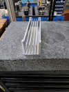
I got the fins cut on the first piece. I'm pretty happy with how it came out. The second piece is cutting now. I thought it might warp a bit when I removed all that stock, but it stayed surprisingly flat. I'll still take a finish pass on the mounting surface when I put the holes in. I should receive my resistors and fans today. I've decided to add the stand-offs to the resistor side so it can be flipped for heavy loads, as @Bill Ferris suggested.
 

Attachments

  • 20260702_112223.jpg
    20260702_112223.jpg
    144.9 KB · Views: 17
  • Dummy_Load_Heatsink_5.png
    Dummy_Load_Heatsink_5.png
    119.3 KB · Views: 16
You just reminded me of one of the first places I worked. One of my jobs was running horizontal mills cutting slots in tubes all day. But no, I don't have that, I'll be machining the fins with a .25" dia, .03 corner radius end-mill. I drafted the sides of the fins slightly and will step it down with light cuts. I was hoping to have one cut today but a few things came up so I didn't get to it. It's ready to go for the morning. It should take a little over 3 hours each, unless I have to slow it down more than I figured because of how far the cutter hangs out. You're right that there is a lot of scrap cutting from solid, around 65%, but I'm using what I had leftover from a bar after finishing a job.

I could add some tapped holes to the corners to accommodate stand-offs. I was thinking the fan blowing through the channels would work well enough, but it's easy enough to add the provision to flip it over.

I was thinking I'd get them anodized when I have some other parts to send out. I was just going to do it for looks, I didn't know it would make a difference on the cooling.

I appreciate all the input from everyone. Thanks!
A properly chosen fan would be fine blowing through the fins with properly sized/located vents in the case to directly pass the moving air in and out of the enclosure with the resistors underneath if you wish to use active cooling.
My suggestion was for the best simplified natural convection passive cooling performance.

Your dummy load, your choice.
 
A properly chosen fan would be fine blowing through the fins with properly sized/located vents in the case to directly pass the moving air in and out of the enclosure with the resistors underneath if you wish to use active cooling.
My suggestion was for the best simplified natural convection passive cooling performance.

Your dummy load, your choice.
Check out my last post, I think the rendering shows what you are suggesting. If not, please correct me. I may someday figure out an enclosure for it, but for now I plan on just sitting it on the bench as is.
 
Check out my last post, I think the rendering shows what you are suggesting. If not, please correct me. I may someday figure out an enclosure for it, but for now I plan on just sitting it on the bench as is.
Ok then passive cooling configuration for now.
 
... I was thinking I'd get them anodized when I have some other parts to send out.

Well, THAT'S just over the top (see what I did there?).

Any enclosure might tend to contain heat/prevent dissipation. With a small pancake on the end, it might not be a measurable difference, however.
 
My dummy load is just a piece of finned extrusion sitting on the bench. Only once in its life have I ever needed to point a fan at it. I did add an aluminum plate to mount some banana jacks for easy hook-up.

The ultimate dummy load would, of course, be water cooled. It would be switchable for at least 4, 8 and 16 ohms. It would include switchable reactance to simulate actual speaker loads. It would have a small uP board and an LCD display so it could display voltages and power output, along with a clipping indicator. The deluxe version would also display %THD.

Or, we could slap some resistors on a heat sink and get on with fixing things!
 
Last edited:
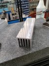
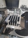
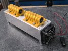
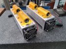
Just about got them done. I finished machining the heat sinks. I still need to make the little bus bars. I'm pretty happy with how this project went. I appreciate the input from everyone.
 

Attachments

  • 20260702_151041.jpg
    20260702_151041.jpg
    131.3 KB · Views: 30
  • 20260702_170613.jpg
    20260702_170613.jpg
    83.6 KB · Views: 19
  • 20260702_172153.jpg
    20260702_172153.jpg
    134.3 KB · Views: 24
  • 20260702_173827.jpg
    20260702_173827.jpg
    145.8 KB · Views: 23
Back
Top Bottom