• The move to the new server is done. There are some software and database maintenance updates in process. This has us passing the hat around to help out. We appreciate any donations. Seriously, even a dollar helps. The payment page may be found here - https://www.audiokarma.org/support.html

Dynaco A430 homebrew, from Jerry.

trainbuftony

Electron Herder
I got this pair from a fellow at work, the thread about how I got them ran its course and as promised I'm going to rebuild them. This thread will have that information in it and then there won't be 6 extra pages on how I found it and all of that other stuff. I found these from a guy at work, he took them out because he heard me talking about tube equipment and I made him an offer he couldn't refuse. He's 82 years old and probably doesn't have any interest in ever fixing stereos again after having done it professionally for 30 years.
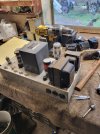
This is how they arrived hand built, and unmolested.
20231013_145233.jpg20231014_080242.jpg20231014_080238.jpg20231014_080246.jpg

I had a project occupying the front burner at that point and couldn't put them on the bench. I put them upstairs in the queue and let the ideas brew in my head as they do... My thoughts were to either mount them on rack panels and use the bottom as the face, or to build a bottom panel and wrap them in a walnut skirt.
I opted to go the way of the walnut skirt so my first order of business was to clean off the sides of unwanted mumbo-jumbo and relocate all of the necessary connections to the "back" pannel, the transformer end.
Tubes naturally want to be up front, on display with the "big iron" right behind them. Today I finished mounting terminal strips, iec jacks and rca jacks on both amplifiers and got them ready to fire up and check out.
Often times when you find a piece of diy equipment you'll discover that the builder used unconventional means to attach speakers to their system, signal wires are the same way. They used funny deutz plugs because they probably had those and lacked a parts express catalog and smart phone. So before I even think about firing this up, I need to get the connections figured out. That's done.


The other thing that must always be done before applying power to a dormant amplifier is to replace all of the electrolytic capacitors. I find they don't age well and I change them out for new. Every electrolytic, every time.
The guy who built this particular amp must have had a head on his shoulders because rather than using the conventional clamps, or mounting wafers, the builder of this amp put all of the electrolytic caps on tube bases, plugged into tube sockets. A full recap takes under 1 minutes time. You simply unplug 4 old caps and plug back in 4 new caps.
Hayseed will make em with octal bases.
My mind is completely blown.

Anywho... today is the day we fire one up and see weather it makes any power!
They've been recapped, the inputs and outputs figured out, and extra parts have been removed. I love how my cloth wrapped wire blends seamlessly with the antique cloth wrapped wire that's already here...
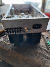
20240107_084212.jpg20240107_084120.jpg
 
Register to hide this ad
The first amp I tested I got to about 25 watts (14v rms across 8 ohms) before it began to mutilate the sine wave. It was at about 3% total harmonic distortion.
I set the level to 1 on the dB scale to get a sense of the frequency response. At 10hz it was a bit over 1 dB down. When I clicked it over to the high frequency it started to squeal (plugged into a dummy load) and the squeal began to get louder, so I pulled the IEC power cord right out of the jack and called that enough for now.
They're going to need more work, obviously, but firing them up was fun and it at least proves out the transformers and whatnot. Good times!
 
I drew up this schematic, in order to try and get a handle on what they're doing here. The power supply seems to be way too high impedence and they've got a funny cathode follower driver arrangement which I've never seen before. Comments, questions, consternation...
Power tubes are EL34/6ca7
Both preamp tubes were 12AT7 when the amplifier arrived and they still are.

I should be able to reconfigure this hardware into a viable 50 watt amplifier wouldn't you think?
Stay tuned.
 

Attachments

  • 20240107_120842.jpg
    20240107_120842.jpg
    120.7 KB · Views: 93
looks like the middle tube is being used as a cathode follower. Normally the reason you do this is to run grid current on your output tubes, meaning they run in AB2 mode. Potential is a bucket load of power, but only if the power supply is stout enough to feed it. Otherwise its basically just there taking up space. You could simply bypass that whole second tube and re-jigger the bias supply slightly and it would be a pretty conventional amp. Probably needs a decent bit of input signal to make full output but other than the low gain its more or less an ST-70 circuit, just with a triode instead of a pentode up front. Or its a Williamson without the second tube, depending on how you prefer to look at it.

It does give the same low impedance source to both grids, which is something a split load doesn't do on it's own but most of the time that isn't a big issue. Lots and lots of amps ran split load inverters and got along just fine.

the way they did the bias supply in this is slightly weird, but I guess it works. The other way to do it is basically the McIntosh method, where the cathode of that driver tube is tied to the negative supply, and it pulls the voltage up to the grids.
 
I should be able to reconfigure this hardware into a viable 50 watt amplifier wouldn't you think?

Well, the (without the cans) Dynaco A430, and the later A431, which also has a 4Ω tap, were what was used in the Dynaco MKII & MKIII amplifiers. You can get a lot of horsepower out of these 20 to 20K. If you're willing to sacrifice a little bandwidth, you can get a heck of a lot more.

I wonder if what you've got isn't a variant of the modified Williamson shown in fig. 2?

 
Somewhat of a strange design. Class AB2 is not possible because of what appears to be cathode bias, and the use of grid 1 stopper resistors. Also, cathode follower drivers don't get much more power from a UL or Pentode output stage anyway because the tubes can already be driven to saturation current levels in Class AB1 -- and once the tubes are saturated, they're saturated. Bet it's fun to play with though!

Dave
 
That's a nice find! Direct coupling can be beneficial. It eliminates blocking distortion that otherwise occurs when coupling caps are charged by momentarily grid current in the output stage. OTOH, I don't believe it's truly useful in an amplifier like this, and it might create issues regarding bias stability. If these were mine, I would consider applying fixed bias and revising the phase inverters to a more typical LTP configuration.

Jack
 
LTP with a single triode gain stage in front of it would be a reasonable setup. Basically a Mullard 5-20 at that point. +1 on the fixed bias too.

in a 9 pin socket I don't think you have many single triodes, but there are some small signal pentodes that can be triode-wired. Can also just use one of the common 12A*7 types, but light only half of it. Set each amp up to use the opposite half, so when they wear out you can flip them and get a fresh triode to work with.

other option, you should be able to use half a 12a*7 as a voltage amp and the other as a CCS load for the LTP.
 
in a 9 pin socket I don't think you have many single triodes, but there are some small signal pentodes that can be triode-wired.
The EF86 in triode mode produces an extremely linear gain stage. I have a sleeve of NOS Mullards, but have never needed to use them because the equivalent Russian 6J32P is also excellent in this mode (and much less expensive). A triode-mode 6J32P feeding a 12AT7 LTP would exhibit plenty of gain and excellent headroom in an amplifier like this.

Jack
 
Is there any sense in coming up with a negative supply and keeping the direct coupled driver, but running it with the cathode negative?
Clearly whoever built this had some healthy curiosity about him...

Obviously a person could easily convert it to be a dynaco mark 2 and it would probably work just fine that way for a long time. These Clearly aren't dynaco mk2s and each one takes up nearly as much space as a pair of mk2s... I am tempted to do some experimenting to see if I can get closer to the rated power out of this setup but I've never really experimented with direct coupling the cathode to the grids. Does anyone care to share the pitfalls?
 
Is there any sense in coming up with a negative supply and keeping the direct coupled driver, but running it with the cathode negative?
My 211 SETs do exactly that. Each amplifier drives the output tube from the cathode of a choke-loaded 6BL7. The bottom of the cathode choke is fed from a stiff negative supply, and the driver has its own power transformer and filter for B+. This provides very linear operation when signal levels push the output stage into A2. I had problems in the prototypes with bias drift, and eventually designed an opamp-based circuit to stabilize the quiescent voltage at the driver cathode. I have no idea whether the design you're working with will experience this issue, but It wasn't simple to resolve. My suggestion is to measure the DC voltage drift at the output stage grid over a period of about an hour from a cold start. This will allow you to make a more informed decision as to the options.

Jack
 
Just to add, earlier points by @gadget73 and @dcgillespie regarding A2 operation are valid and would also need to be considered if you want that capability. As Dave said, the grid stoppers will interfere with A2 operation. They're not required with low mu power triodes like the 211, but it would be risky to remove them from a pentode UL stage.

Jack

​

​

 
Just for fun, last night I drug down one full milk crate of my radio and television news magazines in order to quickly scour them for information that pertains to this set of amplifiers, I found an article in November of 55 by Keroes about a 6550 ultralinear Williamson.

My mother was in the womb when that was printed.

In June of '56 they published one by David Hafler about a 50 watt amplifier which we all know as the MK2 dynakit.

I've got another crate to go through before I really dig into any of the articles, and I know there is at least one more article. As of right now, I'm leaning towards building the Williamson front end because it wouldn't leave me with an extra hole.
I could do the mk2 front end but then I'd have an empty hole and some asymmetry where there once was symmetry.
Naturally I'll keep you all up to date on my findings and progress.
I'm having a great time flipping through the magazines, and realizing how blessed I am to be able to experience this hobby as one would have experienced it when it was state of the art via this Magazine collection.
There's an index of advertisers in the back, which is where I often start in order to poach photos from advertisements.
It's a wealth of really interesting information.
 
Last edited:
If you're going Williamson, 6CG7 tubes are essentially a 9 pin 6SN7 so you can recycle the existing holes. Same with a 6FQ7. One has a shield between the sections and the other does not, but I can never remember which is which. For this purpose I doubt it makes any difference.
 
Just for fun, last night I drug down one full milk crate of my radio and television news magazines in order to quickly scour them for information that pertains to this set of amplifiers, I found an article in November of 55 by Keroes about a 6550 ultralinear Williamson.

My mother was in the womb when that was printed.

In June of '56 they published one by David Hafler about a 50 watt amplifier which we all know as the MK2 dynakit.

I've got another crate to go through before I really dig into any of the articles, and I know there is at least one more article. As of right now, I'm leaning towards building the Williamson front end because it wouldn't leave me with an extra hole.
I could do the mk2 front end but then I'd have an empty hole and some asymmetry where there once was symmetry.
Naturally I'll keep you all up to date on my findings and progress.
I'm having a great time flipping through the magazines, and realizing how blessed I am to be able to experience this hobby as one would have experienced it when it was state of the art via this Magazine collection.
There's an index of advertisers in the back, which is where I often start in order to poach photos from advertisements.
It's a wealth of really interesting information.

The Hafler and Keroes Williamsons are pretty much the same, with some minor component value changes. One thing to be careful about with these designs are the low-frequency stabilization features in the coupling circuits to the ouput tubes. These put a healthy positive voltage on the 6550 grids, which is then counteracted by the large negative bias supply. It's extremely important to mind the resistor values, otherwise you end up with positive voltage on the grids, with unpleasant results. ;-)
 
Just for fun, last night I drug down one full milk crate of my radio and television news magazines in order to quickly scour them for information that pertains to this set of amplifiers, I found an article in November of 55 by Keroes about a 6550 ultralinear Williamson.

In June of '56 they published one by David Hafler about a 50 watt amplifier which we all know as the MK2 dynakit.

I have decades of those mags myself, and there's nothing better than sitting in my comfy chair with a good coffee reading all of those old articles. :) :):)

I remember that one of those articles you mention, Keroes or Hafler, showed the UL or MKII with a totally different driver tube, not the 6AN8 that was actually used in production.
Could you take a look for me? Might have been a 6AU8, 6AW8, or something in that series?
 
Back
Top Bottom