• The move to the new server is done. There are some software and database maintenance updates in process. This has us passing the hat around to help out. We appreciate any donations. Seriously, even a dollar helps. The payment page may be found here - https://www.audiokarma.org/support.html

Dynaco mk III re-animation guidance please...

dogwan

Dogwan
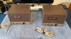
Recently I stumbled on a nice original condition pair of Mk. III's. The gentleman I bought them from said he had them for about 10 years. He got them as part of a large purchase from an estate directly from the original owner, but he couldn't tell me how long it had been since that gentleman had fired them up. So, it's been at minimum of 10 years, but likely much longer.

Let me just say right from the get-go that I am in no hurry and already have a long term plan which includes complete re-cap and new driver boards. For the immediate future, I just want to get them ramped up to verify they are functional. Mostly I want to make sure all the transformers are in good shape.

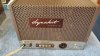
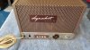
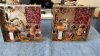
Here's what I found upon initial inspection. Let's call the amp on the left "Amp A", and the right one "Amp B".

Physical inspection:
Amp A:
Stock size fuse in good shape.
Power switch non-functioning (and fell apart when I pulled it to clean contacts)
All solder joints look decent even if old

Amp B:
12 amp ceramic fuse in situ (already replaced with stock value)
0.1uf film cap on driver board broken loose from lifted solder pads (repaired with jumpers to next solder pad in circuit)

Tube test on a Sencore MU140 for emission and leakage only:
Amp A:
GZ34 (Triad labeled, Made in Great Britain) - test good
6AN8 (Westinghouse) - Test bad on both halves
6550 [V1] (National C, Made in China) - Test good, but very very slow to start emitting
6550 [V2] (National C, Made in China) - Test good

Amp B:
GZ34 (Sylvania labeled, Made in Great Britain) - test good
6AN8 (RCA) - Test good
6550 [V1] (National C, Made in China) - Test good
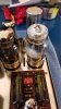
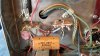
6550 [V2] (National C, Made in China) - Visually very bad, see pic. Doesn't even register on the tester.

Preventative measures already taken:
Cleaned layers of gunk and greasy dirt off chassis and driver boards
Replaced Selenium rectifiers with 1n4007 diodes (both seleniums measured good so not blown....yet)
Performed diode mod to rectifier socket (again using 1n4007's)
Cleaned and tightened tube sockets

So basically I have a complete set of tubes to at least fire them up one at a time. I also have a variac. My question is two-part.
1, do y'all think I'm in a good position to ramp up each amp slowly to test for basic functionality, and...
2. what is the recommended ramp-up schedule? Tubes in or out?
20191128_125337.jpg 20191128_125547.jpg 20191128_125542.jpg 20191128_125537.jpg 20191128_125530.jpg 20191128_125347.jpg 20191128_125342.jpg
 
Last edited:
Register to hide this ad
Here's some more pics.

My plan is to down the road do the following:
Order a higher rated can cap (the 80/40/30/20 550v one from Dynakit parts)
Install theVTA/Tubes4hifi octal driver boards.

Already ordered new 11a switches and CL-80 thermistors.

Also note: my wall voltage is a rock-steady 120.1 volts all year round (I live 1 block from the local sub-station).
20191128_125636.jpg 20191128_125828.jpg 20191128_125809.jpg 20191128_125752.jpg 20191128_125747.jpg 20191128_125704.jpg 20191128_125641.jpg
 
1-Connect speakers
2- replace broken 6550 with a new matched pair
3- replace broken mains switch
turn on, adjust bias , listen for problems

Then, after careful testing and usage for several hours, noting any disrepances, replace more stuff
as needed
 
I would just get and install the replacement can caps, film caps on the board and electrolytic caps underneath. Install them with like for like values, and keep the existing board till you are familiar with it. The can cap might re-form but I wouldn’t keep the others anyway. If you replace the others but keep the can, ramp the voltage up slowly on your variac, after it starts conducting. If no variac, or even if you do, build a dim bulb tester and use that in circuit. Always have speakers connected. And adjust bias when applying full power.

You can do a safe first test of the power transformers for shorts by leaving the rectifier tube out, but obviously this will only test it and filament continuity.

You can check the output transformers without power on (!), simply by measuring the resistance of the windings, eg on the primary side, centre tap to screen and plate connections, and for continuity on the secondary side to the various 4, 8 and 16 ohm connections.
 
Thanks @petercapo , I will follow a 12-hour schedule (10v per hour on primary) to ramp these up after the unknown length of dormancy.

That's very interesting about the wax coating on the underside of the boards. I have never heard of that. FWIW, I only cleaned the top side. Mostly because of the amount of dust coating everything that had a greasy quality. I was a little worried about any chance of conductivity between the components. But also, because it just looked bad.

SurplusGizmos up here is having a black Friday sale and I should be able to grab some 47 or 56uf/100v lytic caps for at least the ones on the underside tomorrow morning.

I have done a preliminary verification of the wiring on both amps and they both look to match the manual. I will do a more thorough walkthrough before firing each one up. Also, they appear to have been built as a pair by the same person. Very few discrepancies in the layout of the wiring, soldering technique, and orientation of parts (I think that's a good sign).

As far as replacing the driver boards, I will eventually get them up and running stable with the stock boards for a while. I am just admitting upfront that I will probably do what I always do and start hot-rodding them. Mostly I am really interested in the ability to adjust the bias individually on the output tubes and like the fact that that feature is built into the Tubes4hifi boards without modifying the chassis.

I have also been reading a lot about the consensus that with the stock driver boards these amps are little rolled off at both ends. I know, I know, don't believe everything you read on the internet. But still, these were designed and built in the '60s and were trying to achieve a different acceptable performance level at the time at a price point [I've owned cars from the '60s with generators and it was worth upgrading to a modern alternator wherever possible - it was nice to not have the wipers slow down when you turned on the headlights - just an anology] I will continue to do my research though before I get there.

About 5 or 6 years ago a friend asked me to work on his ST-70 that he had started installing a Van Alstine upgrade. I think it was the "Super70i" kit. He got stuck about halfway through and stashed it in a closet until he brought it out years later and asked for my help (I think he said he bought the kit in the late '90s?). Since the kit replaced all the suspect caps I didn't have to worry about ramping all the vintage parts back up. I ended up tearing out the whole kit and started over with new hook up wire and found a few mistakes and lots of bad soldering on the board. Got it all sorted and it worked great even though the B+ ran at the upper limit of tubes. Also had a few issues with getting a good rectifier until we put in the diode mod. Now the kicker, another friend had a stock ST-70 with the exception of having been recapped, even had a good pair of matched 7199's installed. He brought his unit over to my house before I returned the converted Super70 to my other friend and we spent an afternoon comparing. The memory is faded now, but I recall being impressed with the differences. Mostly the increased transient response, clarity, and bass slam. That experience also contributed to my inclination to look at swapping out for modern driver boards. If I hadn't had the opportunity to do a direct comparison I could have been very happy with the stock ST-70. (although I do acknowledge this was not a measured laboratory experiment, just a fun exercise)
 
Don't hesitate about the MkIII 's qualities. If left in stock form ( with fresh tubes can caps etc) it will
perform as per the manual. 60 w power and a flat respons within 20 - 20khz.
If this is not what is wanted i suggest you get them running unmolested , sell them unmolested as
this will get the most value of them, and buy or build what you want.
 
Don't hesitate about the MkIII 's qualities. If left in stock form ( with fresh tubes can caps etc) it will
perform as per the manual. 60 w power and a flat respons within 20 - 20khz.
If this is not what is wanted i suggest you get them running unmolested , sell them unmolested as
this will get the most value of them, and buy or build what you want.

Thanks Peter, ROI is not a concern. But I take your point.

With vintage equipment, when I do make modifications I always save all stock parts and avoid physical alterations to the hardware unless absolutely necessary.
 
Thanks @petercapo , I will follow a 12-hour schedule (10v per hour on primary) to ramp these up after the unknown length of dormancy.

That's very interesting about the wax coating on the underside of the boards. I have never heard of that. FWIW, I only cleaned the top side. Mostly because of the amount of dust coating everything that had a greasy quality. I was a little worried about any chance of conductivity between the components. But also, because it just looked bad.

SurplusGizmos up here is having a black Friday sale and I should be able to grab some 47 or 56uf/100v lytic caps for at least the ones on the underside tomorrow morning.

I have done a preliminary verification of the wiring on both amps and they both look to match the manual. I will do a more thorough walkthrough before firing each one up. Also, they appear to have been built as a pair by the same person. Very few discrepancies in the layout of the wiring, soldering technique, and orientation of parts (I think that's a good sign).

As far as replacing the driver boards, I will eventually get them up and running stable with the stock boards for a while. I am just admitting upfront that I will probably do what I always do and start hot-rodding them. Mostly I am really interested in the ability to adjust the bias individually on the output tubes and like the fact that that feature is built into the Tubes4hifi boards without modifying the chassis.

I have also been reading a lot about the consensus that with the stock driver boards these amps are little rolled off at both ends. I know, I know, don't believe everything you read on the internet. But still, these were designed and built in the '60s and were trying to achieve a different acceptable performance level at the time at a price point [I've owned cars from the '60s with generators and it was worth upgrading to a modern alternator wherever possible - it was nice to not have the wipers slow down when you turned on the headlights - just an anology] I will continue to do my research though before I get there.

About 5 or 6 years ago a friend asked me to work on his ST-70 that he had started installing a Van Alstine upgrade. I think it was the "Super70i" kit. He got stuck about halfway through and stashed it in a closet until he brought it out years later and asked for my help (I think he said he bought the kit in the late '90s?). Since the kit replaced all the suspect caps I didn't have to worry about ramping all the vintage parts back up. I ended up tearing out the whole kit and started over with new hook up wire and found a few mistakes and lots of bad soldering on the board. Got it all sorted and it worked great even though the B+ ran at the upper limit of tubes. Also had a few issues with getting a good rectifier until we put in the diode mod. Now the kicker, another friend had a stock ST-70 with the exception of having been recapped, even had a good pair of matched 7199's installed. He brought his unit over to my house before I returned the converted Super70 to my other friend and we spent an afternoon comparing. The memory is faded now, but I recall being impressed with the differences. Mostly the increased transient response, clarity, and bass slam. That experience also contributed to my inclination to look at swapping out for modern driver boards. If I hadn't had the opportunity to do a direct comparison I could have been very happy with the stock ST-70. (although I do acknowledge this was not a measured laboratory experiment, just a fun exercise)
When using a variac to bring up voltage to something, don't forget to place an AC ammeter in series with the 'hot' lead going to the tube amp. Otherwise, you'd have no idea whether or not anything might be going awry with the filter capacitors or other parts of the amp which might cause too much current to be drawn, which could lead to things burning up anyway. :eek: In lieu of an AC ammeter, you could use a 1 ohm 10 watt power resistor instead, and then connect a multimeter set to read AC volts across it to read amps. More info on both methods can be found on this page. Good luck!
-Adam
 
Last edited:
I have with some success cleaned these boards with 96% alcohol followed by a layer of shellac .
Shellac may be used over all components when they are dry, and will evaporate nicely at
solder pads when soldering.
 
Well, poop! I washed (cleaned) the top side of the driver boards with Q-tips and 91% isopropyl alcohol prior to starting this thread. Nothing leached onto the bottom side and the wax coating is still intact there. I wish I had known how delicate these boards were. My prev. experience working on PAS3 and an FM3 let me know how easy it is to lift traces, but who knew you had to worry about the board becoming conductive as well!

Fortunately, I'm not seeing much evidence that these were stored in a damp climate. But at the same time, the PNW is always dampish unless you have a climate-controlled house. I do think things are much worse in humid climates for vintage stuff. I've not seen things fare well in places like Florida.

Thanks @AdamAnt316 , I had forgotten about monitoring the current when ramping up things. I was last really into DIY tube stuff about 10 years ago and was just starting to really learn some stuff when I veered into SS for the last decade. Your comments caused me to dig in the parts bin and I had an unopened package of 1Ω/10w resistors purchased for just this exact purpose. Had forgotten all about them. Fortunately, I bought another Variac yesterday. This one is a 10A version with a built-in ammeter. SurplusGizmos up here in the silicon forest always has great stuff and they were having a Black Friday sale. It's a Tenma, looks mint, and also looks to be of good build quality. I will use my Fluke multimeter to verify and/or calibrate the voltage and amp scales.

I totally agree with everything you said @petercapo and I'm not arguing against your stance. I don't think I did a very good job of communicating that my ST70 story was just that, and not evidence that the ST70 in stock form did not compare to the modified one.

Again, I have every intention of getting these MKIII's up and running with the stock circuit and use them for a while before doing any alterations. But at the same time, I do reserve the right to pursue a modification path for my own reasons. And here, I would like to share another analogy as a way of communicating my own personal motivations:

My personal experience with vintage audio (and other hobbies that are similar) is that when discussing what to do with the items that endear our hearts to the hobby, that the conversations tend to be very polarizing along a spectrum. On the one hand, there are the camps of restoring everything to original and honoring the piece for what it is/was. And, at the other end of the spectrum are the tweaker and modifier camps who are chasing the dragon of incremental performance improvements (validated or not). There doesn't seem to be much in the middle.

I tend to fall in the middle of these discussions and when posting online I find that often this middle stance is often interpreted as being on the opposite end of the spectrum from one camp or the other. On the one hand, I don't feel the need to second-guess the engineers who are infinitely more qualified than I am (no matter how long ago), but on the other hand I really do enjoy trying things out and seeing where it goes.

When I was in my 20's I used to run around with the vintage MC crowd. There was a big crossover with my main peer group of bike messengers and grunge rockers of the 80's and early 90's in Seattle. This vintage MC crowd had a few distinct subsets. I.e., the Japanese vintage crowd, the vintage euro crowd, etc. Among those subsets also came the same similar camps of originalists and modifiers (street fighters, cafe racers, and rat-rodders, et al). At the time I had a minty '75 CB400f. It was completely stock, had low miles, and beautiful to behold. These bikes were notorious for getting chopped up and modified. The fact that mine was completely original was a point of pride to the point of fetishization. But, the longer I hung out with the modifiers (cafe and rat bike crows) the more I realized it was not so much about actually ending up with a better bike, but more about the journey, the process, the camaraderie, the one-upmanship, and actually getting your hands into the bike. When one of my friends suggested I do a front end conversion on my bike so I could have dual discs up front, at first I balked. It wouldn't be stock anymore. But then the more I thought about it, the more I realized it would be fun and even though the stock brakes were fine for the original design intention of the bike, I definitely rode the bike harder than it was intended for. More stopping power would actually be nice. I sold the bike before I ever did the conversion, but was perfectly willing to do it because I knew it could be reversed without inherent damage to the bike. Ever since then I've stopped coveting things in their original shape unless they were absolutely a rarity. The value for me in owning a possession is it must bring me joy or it's gone. And if it brings me joy to tinker, modify, and get my hands dirty then I will do that. I was the same way when I was a custom woodworker. I would get just as much joy out of making the perfect version of a design, as I did owning, tuning, modifying, and using the tooling. I owned some very valuable and collectible vintage hand tools and they all got used on a regular basis.

OK, so back to the MKIII's.....

Yesterday I performed continuity tests on the power and output transformers. I did this in situ with the tubes removed. Everything checked out. No differences between amps or variations in resistance. Also no continuity between primaries and secondaries. So short of unhooking the transformers to test out of circuit I think there is no initial indicators that there is anything wrong (so far). Fingers crossed that when I start applying voltage that hidden problems don't show up.

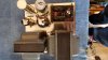
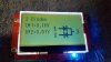
Now, I did discover one discrepancy. On amp B (the one with the blown tube) the 30 and 20uf (square and half-moon) sections of the can cap before and after the choke tested as double diodes (see pic). But then this morning I tested again and only the 30uf section tested as dual diodes. The 20uf section tested as a capacitor. This was done with one of those cheap Ebay component testers which I know are not wholly dependable (but it is cheap and handy). All other caps on the underside did test as caps (no shorts) even though the values were all over the place. I am hoping that a lot of reforming will happen when I do get around to starting them up on the variac.

I did check both the chokes in situ and both measured as ~60Ω resistors. I think I would have to disconnect them to get them to read as chokes.

20191201_143324.jpg

Yesterday I was hoping to get some 47-100uf/100v caps but they were all cleaned out of those values. I do have some 220uf/100 caps. Would these be too high capacitance to replace the 50uf/75v cardboard polarized (bias) caps?

Also, I found some 0.22uf/2000v film caps. No luck on the 0.1 caps. Should I even bother replacing the Pyramid caps yet? What is the minimum voltage to replace the 0.1uf Pyramid cap?

20191201_150144.jpg
 
Last edited:
Understood, they are yours to do with as you please. Just to be clear, my intention is not to be polarizing. When I post, I keep in mind that others in similar circumstances are likely watching, so my comments are for anyone who might benefit. Endearment has it's place, but I try to sort out facts from fiction so that folks can make better informed decisions.

Yes, absolutely agree. All of us need to keep an eye on the perpetuity of our threads and the statements therein. FWIW, your comments definitely got me thinking.

For the bias caps... I can't think of any data I've seen about a maximum here. But, based upon discussions of things like current inrush, increasing power supply capacitance and such, going to two 220µF is more than four times the original amount. If it were me, and given the lack of relevant data, I wouldn't put in that much.

Yeah, that's what I thought. Worth asking though.

For the IMP capacitors on the PCB...

Looks like I need to cool my jets and get together a small-cap order before going too far. Starting to think a quick $20-30 order could be good insurance to a good initial test before ordering the replacement can caps and new tubes.

How do the 12, 390, and 750 pf caps hold up?
I have the following on hand:
12pf/1000 Ceramics
390pf/600 Polyester
820pf/500 Silver Mica

Gah! Now I'm thinking a resistor order would only add a few dollars and save on shipping later. Do you have any input on whether or not to preemptively replace all those old carbon comps with Metal Films or Carbon Films (as opposed to pulling and testing each resistor)?
 
Almost forgot... thought I'd mention that 2,000VDC capacitors is well beyond what is needed - do they even fit in the available space?

Yeah I knew 2000v was way overkill, but they were only $2 each so I couldn't resist even if I don't use them on this project. And yes, they will totally fit.
20191201_165940.jpg
 
https://www.mouser.com/ProductDetail/Cornell-Dubilier-CDE/940C20P22K-F?qs=s9amlvmP6ExH7ijv4UEGBg==

Polypropylene. Although if you pull the datasheet the construction diagram shows Metalized Polypropylene, Polypropylene, Metalized Polyester sandwich. Looks like it was made/marketed as a Pulse, Snubber cap. Probably shooting from the hip to use it as an audio coupling cap, but hey what the hell. It probably won't blow it up. And I doubt it would be any worse than 50 year old Pyramid caps?

http://www.humblehomemadehifi.com/Cap.html

Scroll about 1/3 down to the Cornell 940c and it actually scored pretty good on this comparison page* when used as crossover caps. He raves about the high voltage ones used as bypass caps. I was surprised to find this when I was googling this cap for audio use. Maybe I should have bought more.

*I've looked at this page before and have used it as a reference in the past for crossover caps. Mostly to make sure a cap is not garbage if I was trying to choose my parts list.
 
I have found restored stock (new stock design driver board) these are very capable.
If you opt to SS the rectifier, you can use the 5v filament winding as a bucking winding. (Food for thought)
 
Well, maybe you've finished your project by now. But I put the VTA/Tubes4HiFi "classic" input board into my Dynaco ST-70, and it made and amazing difference in the quality of the sound. While I expected (and got) more transparency in general, what really surprised me was the bass extension. Even though I'm driving a pair of Definitive Technology BP7001SC towers with powered subwoofers, the original Dynaco was (as it turns out) light on bass. The new input board fixed that.

I've also been reading recently about old amplifier technology. It turns out that weak bass response might be a feature and not a bug. In the day, turntables were the main source of quality audio. But feedback was a problem. Some amp manufacturers apparently weakened the bass to compensate. I have no idea whether this was practice at Dynaco, but my experience certainly doesn't contradict it.

Let us know how your project is coming along, or how it turned out.

Cheers,

Kim G
Boston, MA
Where I'm ever-so-slowly restoring a pair of Heathkit W-5Ms.
 
As I recall, independent test reports back in the day, for example Stereo Review / Hirsch-Houck Labs and others, verified the published specs for the original Stereo 70, namely: Frequency response +/- 0.5dB from 10 cps to 40 kc and Power Response of 20 cps to 20 kc within 1 dB of 35 watts at less than 1% distortion. That's pretty good. And, Dave Gillespie's recent study corroborated the original Stereo 70's performance http://www.audioregenesis.com/documents/ST-70 Base Line Testing.pdf

It may be that your original Stereo 70, for one reason or another, was not performing up to its original specifications. Simply replacing the driver with another that is properly configured, with all fresh parts, and maybe also some fresh power supply parts, may be what made the difference.

In any case, I've never experienced a shortage of bass from my Dynaco amps with the possible exception of my Stereo 35, and this may simply be due to it being a lower powered amp to begin with and having smaller OPTs.

Indeed, you are probably correct. My original input board had a bunch of out-of-spec resistors. I had replaced the bypass caps, but that didn't make much difference, even though the old ones were leaky. Still, it's not totally fair to compare a bunch of 50-year old components with fresh stuff. That said, I'm VERY happy with my new input board, and equally delighted to be freed from the need to buy 7199 tubes, which are getting scarce and expensive.

Cheers,

Kim
 
I haven't really touched the Mk iii's since my last post. They are securely stored in my closet right now. Had a few more urgent projects spring up and then my employment situation took a turn just before the pandemic lockdown. However, I am still planning on getting them up and running. Still debating what direction I want to go. Right now I am 75% sure I am going to just go ahead and put in the Octal VTA/Tubes4HiFi boards. They are not very expensive and I really like the dual adjustable bias pots right on the board.

I've listened to the arguments to keep them stock for value's sake and that the original circuit is just as good if fully up to spec. But, for me, I think I will have the most enjoyment out of putting new boards in. I will put the old boards in a sealed bag and store them in a climate controlled environment so that if I ever sell the amps I can include the original parts.
 
Back
Top Bottom