• The move to the new server is done. There are some software and database maintenance updates in process. This has us passing the hat around to help out. We appreciate any donations. Seriously, even a dollar helps. The payment page may be found here - https://www.audiokarma.org/support.html

dynaco pas 2 part list

jayver441

New Member
I'm rebuilding my pas2 and currently looking for parts (mostly resistors and capacitors). Im looking at the manual's part list but its incomplete and missing vital details.

I'm thinking I can create a new list from the schematics, but there's still an isue. The schematics does not label what wattage the resistors sould be rated at nor what voltage the caps can handle. So now I'm stuck.

I need complete list of parts. So, if anyone already have a complete part list, can you post it? If not it would be enough to tell me what wattage the resistors are rated for and what voltage the small capacitors should be.
 
Register to hide this ad
The parts list only contains parts that would be assembled in a kit. The large carbon resistors are 2 W, the small carbon resistors are 1/2 W. I got that from one of the resistor size vs. power rating charts online. Later dynaco manuals have much better descriptions of all components.
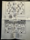
The circuit diagram in the assembly/service manual has all the components on PC's 5 and 6.
Later dynaco manuals have much better descriptions of all components not just those assembled.

I'm rebuiding a PAS2 and bought new boards and tube sockets from Dynakit, a Cap replacement kit from ebay and still have to get resistors. A simpler and not to costly way to go. I've only had the PAS for a few days, it's in good shape, so I'm hoping an easy rebuild.

The cap kit is in a bag but I can give you voltages/uF values for all of them if needed. They are supposed to be the same as original. The quad section cap can be replaced if 4 smaller ones are not what you want.
 
I'd just open up the PAS2 and read the values off the caps and resistors inside the unit. Have never trusted parts lists in a service manual to be completely accurate. Manufacturers change parts as time progressed.
 
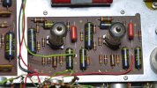
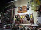
Hopefully these will help. Sorry I didn't find my digital copies but luckily had these filed away. This site really craps out the quality of uploaded images, so message me if you need any of these properly scanned. I have pretty much any Dynaco documentation you could need. As fishee said, larger components on the graphic should be higher watt, but actually 1 watt, otherwise 1/2 watt. Notice the 1 W on the graphic on the first image there on each 100k resistor. Modern metal film resistors are so small compared to old allen bradley carbon comps, so there's no reason not to just use 1 - 2 watt resistors on the entire amp. They'll fit just fine and they'll last for 100 years. Also take care to find resistors that can handle higher voltages - this is often overlooked. I go for Vishay / Dale fireproof style resistors in the tan colored variety that can handle at least 350 volts. You can check documentation of each component when you look it up on Digikey. Coupling caps should be if I remember correctly above 630 volts, as those aqua originals you see in the attached photo. I was very happy running MPT type yellow caps in my PAS preamps and they sound fantastic, they're rated around 6-700 volts, should be absolutely fine.

Lastly, something I've not done but need to investigate - factory wired PAS amps had these caps going from the eyelet board to the controls. Kit systems did not come with these parts nor instructed you to do so. I've yet to figure out what the accomplished but it might be an important improvement, see attached.
 

Attachments

  • IMG_4637.jpg
    IMG_4637.jpg
    120.6 KB · Views: 27
  • IMG_4639.jpg
    IMG_4639.jpg
    88.1 KB · Views: 22
  • IMG_4641.jpg
    IMG_4641.jpg
    146.8 KB · Views: 28
  • FIX THIS.png
    FIX THIS.png
    400.4 KB · Views: 29
Last edited:
Nice pics albusark. Where did the boards pic come from?
Yeah, I looked at the manual schematics and there are some mismatches from my boards.
My PC5 seems different from the schematic above, there are (2) 9.25 k Ohm resistors, the big ones across the top. They're both open.
 

Attachments

  • PC5 closeup..JPG
    PC5 closeup..JPG
    114.2 KB · Views: 11
Shoot I thought it was a PAS 2 diagram, probably is 3X. Anyone have these old diagrams? Anyway, you can just order 1-2 watt resistors and they'll even look small compared to the old components. Check out the Mark 3 amp I finished recently, some of the resistors look tiny on the board but they're 1 watt. The schematic requires 1/2 watt. Again, get the vishay / dale fireproof resistors that are rated for high voltage and you'll be good.
 

Attachments

  • IMG_4451.jpg
    IMG_4451.jpg
    168.7 KB · Views: 9
Last edited:
Those are 1500 pF caps, not resistors, ancient style, my bad.
I have all three service manuals and the boards are the same. The X difference is in the tone controls with a dead spot on center
What I'm doing is using the boards albusark posted (From Dynaco Tube Audio Forum):
https://dynacotubeaudio.forumotion....nd-pc-6-phono-board-on-the-pas-preamps-photos
And using the dynakit populated boards pics to cross reference. I'll be building the dynakit boards, stock configuration.
Here's my resistor list, got all from Newark yesterday, someone might want to look over it for blunders. Follows the Roy Mottram list in the link above.
PC6
1/2 w
1k 4 -
10k 2 -
47k 4 -
100k 2 change to 95.3k -
100k 2 -
150k 1w 2 -
1.2M 2 -
4.7M 2 change to 2.2M - -

PC5
1/2 w
1k 4 -
4.7k 2 -
18k 2 -
47k 2 -
62k 2 -
100k 2 -
470k 2 -
1.2M 2 -

Couldn't find a 95.3K and will read over Roy's comments to see if that and the 2.2M swap is necessary.
 
In rebuilding my PAS-2, I had nearly forgotten about the various resistors going to the Filter and Loudness switches, as well as the Mono to Stereo soundstage/space switch. I had found that the original values, 270K and 560K Ohms on the mono to stereo switch had been replaced with 33K and 68K Ohms in the PAS-2X/3X schematic that I have. (I had already replaced all of the capacitors, which were labeled 'Imp,' with values as close as possible to the originals. Thank goodness for Mouser!)

While possibly an indulgence, I would recommend getting enough of all values of the resistors so that you can match the pairs (usually) with your DMM. Recall, too, that most of the original resistors used had a 10% variance, so getting resistors close to the original value will be just fine. (I used up lots of the 47.4K Ohm resistors I had in place of the original 47K Ohm resistors, for example.) Of course, the 5% and the pair of precision 1% 100K Ohm resistors on the phono board are exceptions and should be replaced with the same value.

Finally, while perhaps not necessary, I did use Wima DC Link (and equivalent) film capacitors in the B+ supply while keeping very close to the original can capacitor values because of that delicate 12X4. I think the first cap is 10 uF, followed by 40, 20 and 20 uF.
 
IMG_4676.jpg

Here's an idea of the components I used to replace those out of spec on this one I use in my living room. MPT type caps have some of the best characteristics for a coupling cap. I used vishay high voltage resistors and silver mica caps for the rarer pF values. Probably cost about $40 in parts. Also put a pair of matched Sovtek LPS 12ax7's, in my experience they're excellent. This is a fantastic sounding preamp circuit, no idea what Bob Latino was on about. I've heard all sorts of modern hi-fi preamps, they focus on making everything sound "inoffensive". Nothing can sound harsh, nothing can be jarring. It's censoring your music! To me nothing beats a great sounding INTERACTIVE preamp. Punk or garage recordings will sound authentic on this equally well as a classical or jazz recording. There's a reason people love these. You can sit and enjoy your music, adjust the EQ for both channels to suit your tastes. Some songs sound better with a bass boost, some are too hot on the treble. I don't care that they're tube amps, I love them for the simplicity of the circuit, ease of repair and great user experience. This thing is 60 years old and it sounds like heaven.

This refutation of Bob Latino's claims is kind of wonderful, he says the amp isn't worthy and he's flat out wrong (and they call him out on his claims).

 
Last edited:
https://www.audioregenesis.com/documents/PAS_Phono.pdf This refutation of Bob Latino's claims is kind of wonderful, he says the amp isn't worthy and he's flat out wrong (and they call him out on his claims).

Note that the AR article is not in reference to Bob Latino at all. In fact, the original source of the claimed RIAA error is here:


This appears to be a modelling exercise which does not reflect the way a properly functioning PAS phono stage actually performs. Whether or not Bob was influenced by this information, I do not know. Claims that the stock PAS phono stage can be modified, by parts selection alone, to achieve RIAA accuracy to within +/-0.1dB are rather optimistic. While this might be approached, for a particular tube, with carefully hand selected components, it will not be the case generally, and will change as the tube ages. This is because there is simply not enough headroom at the low end of the band for the feedback to fully control the gain, as it should. Thus, low frequency response becomes somewhat sensitive to tube gain. IMO, Dynaco chose the best compromise overall.
 
Note that the AR article is not in reference to Bob Latino at all. In fact, the original source of the claimed RIAA error is here:


This appears to be a modelling exercise which does not reflect the way a properly functioning PAS phono stage actually performs. Whether or not Bob was influenced by this information, I do not know. Claims that the stock PAS phono stage can be modified, by parts selection alone, to achieve RIAA accuracy to within +/-0.1dB are rather optimistic. While this might be approached, for a particular tube, with carefully hand selected components, it will not be the case generally, and will change as the tube ages. This is because there is simply not enough headroom at the low end of the band for the feedback to fully control the gain, as it should. Thus, low frequency response becomes somewhat sensitive to tube gain. IMO, Dynaco chose the best compromise overall.
Agreed, I was inferring that his poor opinion of the amp was a result of these rumors that he decided to agree with. He of course may have come to his own conclusion, but as a prominent member of the Dynaco modding community I think he would have played a part in the unsubstantiated claims as he also aimed to "improve" the original designs. I personally don't think Mr. Latino was on par with Ed Laurent & David Hafler, and I think that's a silly argument to make. Thank you for your response I'm a big fan and deeply appreciate your contibution and knowledge.
 
Last edited:
Back
Top Bottom