• The move to the new server is done. There are some software and database maintenance updates in process. This has us passing the hat around to help out. We appreciate any donations. Seriously, even a dollar helps. The payment page may be found here - https://www.audiokarma.org/support.html

Dynaco ST-150 right channel not working.

Hi guys, I just finished doing the Ohm tests from page 21 of the manual but i am not sure if i did them correctly.
I used my Fluke 87 V DMM to do the tests, I took the readings at the bottom of each fuse holder (all the fuses were removed) were the fuse snaps into and these are the readings: F201 363 K Ohm, F202 230 K Ohm, F203 133.9 K Ohm, F204 324 K Ohm. The manual says over 4000 Ohms but it does not say what the maximum should be it just says "Large variations are possible because of differences in types of meters, and variations in output transistors" So are my readings ok or not? Please advice. I need to know if i can proceed to the next step or check wiring connections or faulty components even though i checked all the transistors already and replaced some.
Thank you
i havent read enouph of the service man to understand what the ohm test is looking for. or what that means.
 
it says from the rear of B+ and B - fuse clips to Ground! you should get a reading of over 4000 ohms. with all 4 b+ fuses,and 2 speaker fhses remove. it doesnt sound like your doing somthing correctly. you have four readings not 2. ?
 
it says from the rear of B+ and B - fuse clips to Ground! you should get a reading of over 4000 ohms. with all 4 b+ fuses,and 2 speaker fhses remove. it doesnt sound like your doing somthing correctly. you have four readings not 2. ?
Hi jkerr, I went by what the manual said i connected the ground wire to one of the B+ fuse clips and the other end to the chassy if i remember correctly or maybe the other end i clipped it to the negative lead of the DMM and used to e positive to do the measuring I can't remember its been a while but i can do it again. Buck said that that test was basically useless that it did not help. Right not i am awaiting some parts from mouser so i am at a stand still. I appreciate your help. I ordered some trimmer pots and some transistors to replace a burnt transistor and some zener diodes just in case. I will report back once the parts get here and i install them.
 
Hi jkerr, I went by what the manual said i connected the ground wire to one of the B+ fuse clips and the other end to the chassy if i remember correctly or maybe the other end i clipped it to the negative lead of the DMM and used to e positive to do the measuring I can't remember its been a while but i can do it again. Buck said that that test was basically useless that it did not help. Right not i am awaiting some parts from mouser so i am at a stand still. I appreciate your help. I ordered some trimmer pots and some transistors to replace a burnt transistor and some zener diodes just in case. I will report back once the parts get here and i install them.
It sounds to me like its just a basic short component tests. anything less than 4000 ohms you probably misplaced somthing or have a short. Unfortunatly i dont have one to verffy. Dynaco spent years sending kits out to people. i generaly trust what there manuls say. Before the internet. Most people were using analog meters ans phone calls for support lol. i would fix what you know is wrong and make sure you dont have anything else broken or test bad around that burnt transister before worring about that test. Those old components can start to drift in values. Resistors and caps.
 
Last edited:
It sounds to me like its just a basic short component tests. anything less than 4000 ohms you probably misplaced somthing or have a short. Unfortunatly i dont have one to verffy. Dynaco spent years sending kits out to people. i generaly trust what there manuls say. Before the internet. Most people were using analog meters ans phone calls for support lol. i would fix what you know is wrong and make sure you dont have anything else broken or test bad around that burnt transister before worring about that test. Those old components can start to drift in values. Resistors and caps.
I replaced several transistors so i am hoping that this time i will get better readings, I still have to do the DC offset check. I was reading that some kits were sold by Dynaco complete and ready to go. I have no idea if mine was one of those. I should have my parts by Saturday.
 
Hi guys i am back. I took some voltage readings of the following transistors on board PC 36 and here they are.
LEFT CHANNEL: (A)
Q101 Q102 Q103 Q104 Q105 Q106
E +0.889 vdc E +0.889 vdc E +28.19 vdc E -40.58 vdc E +1.146 vdc E readings not able to take.
C - 39.93 vdc C -40.49 vdc C +4.110 vdc C -1.229 vdc C - 0.669 vdc C
B + 0312 vdc D +0.298 vdc B +27.49 vdc B - 39.97 vdc B +0.538 vdc B

Q107 Q108 Q109 Q110
E +0.002 vdc E -0.073 vdc E +0.536 vdc E -0.667 vdc
C +1.057 vdc C -1.057 vdc C +42.53 vdc C -42.40 vdc
B + 0.037 vdc B - 0.076 vdc B +1.060 vdc B -0.674 vdc

RIGHT CHANNEL: (B)
Q101 Q102 Q103 Q104 Q105 Q106
E +0.999 vdc E +1.001 vdc E +26.73 vdc E -39.82 vdc E +0.772 vdc E -1.583 vdc
C +0.002 vdc C - 39.97 vdc C +7.11 vdc C -1.583 vdc C -1.000 vdc C+0.756 vdc
B +0.417 vdc B + 0.420 vdc B + 26.00 vdc B - 39.27 vdc B +0.206 vdc B -0.994 vdc

Q107 Q108 Q109 Q110
E -0.397 vdc E -0.394 vdc E +0.200 vdc E -1.018 vdc
C +0.662 vdc C -1.481 vdc C +42.40 vdc C - 42.72 vdc
B -0.336 vdc B -0.449 vdc B +0.712 vdc B -1.565 vdc

And these were the voltages on the PC 37 board.
Holes: these should all be positive VAC
#1 +33.73 vac
#2 +33.53 vac
#20 +33.82 vac

#5 +44.03 vac
#6 +43.93 vac
#21 +44.07 vac
These below should be all positive VDC,
#8 +43.20 vdc
#9 -42.94 vdc
#19 -42.65 vdc
These should all be negative VDC
#7 -42.94 vdc
#10 -42.89 vdc
#18 -42.82 vdc
And on the numbered terminals from 1thru 26 on PC 36 board these are the readings a have:
#1, 0.00 ground. #2, +42.2 vdc #3, +42.2vdc, #4, -1.063 vdc, #5, +1.063 vdc, #6, +1.031 vdc, #7, +1.067 vdc, #8, -1.102 vdc

#9,+0.544 vdc, #10, -43.4vdc, #11, -43.4vdc. #12. 0.00vdc, #13, 0.00vdc, #14, 0.00vdc, #15, +.404vdc, #16,-43.3vdc,

#17, -43.3vdc, #18, +.216vdc, #19, -.440vdc, #20,-1.010vdc, #21, -.323vdc, #22, -.383vdc, #23, -.381vdc, #24, +43.2vdc,
#25, +43.2vdc #26, 0.00 ground.
The transistor that i thought was bad was in good shape I have just not soldered properly and had popped out of the mounting holes on two of the leads so i tested it and was good and i re installed it.
I think i might still have a short because the bulb on the dim bulb tester does not go completely out.
I noticed that the right channel upper output transistor is warmer at 104f than the left channel upper transistor at 99f and i can feel the "heat shield fins" are warmer on the right channel. So maybe the short is causing the heat on the output transistors? not sure? What should i be checking? Also some of the voltages are negative when they should be positive on the PC37 board?

 
Hi guys i am back. I took some voltage readings of the following transistors on board PC 36 and here they are.
LEFT CHANNEL: (A)
Q101 Q102 Q103 Q104 Q105 Q106
E +0.889 vdc E +0.889 vdc E +28.19 vdc E -40.58 vdc E +1.146 vdc E +1.067 vdc
C - 39.93 vdc C -40.49 vdc C +4.110 vdc C -1.229 vdc C - 0.669 vdc C -1.222 vdc
B + 0312 vdc D +0.298 vdc B +27.49 vdc B - 39.97 vdc B +0.538 vdc B - 0.624 vdc
NOTE: I was able to take the readings of Q106 left channel and i posted them.
Q107 Q108 Q109 Q110
E +0.002 vdc E -0.073 vdc E +0.536 vdc E -0.667 vdc
C +1.057 vdc C -1.057 vdc C +42.53 vdc C -42.40 vdc
B + 0.037 vdc B - 0.076 vdc B +1.060 vdc B -0.674 vdc

RIGHT CHANNEL: (B)
Q101 Q102 Q103 Q104 Q105 Q106
E +0.999 vdc E +1.001 vdc E +26.73 vdc E -39.82 vdc E +0.772 vdc E -1.583 vdc
C +0.002 vdc C - 39.97 vdc C +7.11 vdc C -1.583 vdc C -1.000 vdc C+0.756 vdc
B +0.417 vdc B + 0.420 vdc B + 26.00 vdc B - 39.27 vdc B +0.206 vdc B -0.994 vdc

Q107 Q108 Q109 Q110
E -0.397 vdc E -0.394 vdc E +0.200 vdc E -1.018 vdc
C +0.662 vdc C -1.481 vdc C +42.40 vdc C - 42.72 vdc
B -0.336 vdc B -0.449 vdc B +0.712 vdc B -1.565 vdc

And these were the voltages on the PC 37 board.
Holes: these should all be positive VAC
#1 +33.73 vac
#2 +33.53 vac
#20 +33.82 vac

#5 +44.03 vac
#6 +43.93 vac
#21 +44.07 vac
These below should be all positive VDC,
#8 +43.20 vdc
#9 -42.94 vdc
#19 -42.65 vdc
These should all be negative VDC
#7 -42.94 vdc
#10 -42.89 vdc
#18 -42.82 vdc
And on the numbered terminals from 1thru 26 on PC 36 board these are the readings a have:
#1, 0.00 ground. #2, +42.2 vdc #3, +42.2vdc, #4, -1.063 vdc, #5, +1.063 vdc, #6, +1.031 vdc, #7, +1.067 vdc, #8, -1.102 vdc

#9,+0.544 vdc, #10, -43.4vdc, #11, -43.4vdc. #12. 0.00vdc, #13, 0.00vdc, #14, 0.00vdc, #15, +.404vdc, #16,-43.3vdc,

#17, -43.3vdc, #18, +.216vdc, #19, -.440vdc, #20,-1.010vdc, #21, -.323vdc, #22, -.383vdc, #23, -.381vdc, #24, +43.2vdc,
#25, +43.2vdc #26, 0.00 ground.
The transistor that i thought was bad was in good shape I have just not soldered properly and had popped out of the mounting holes on two of the leads so i tested it and was good and i re installed it.
I think i might still have a short because the bulb on the dim bulb tester does not go completely out.
I noticed that the right channel upper output transistor is warmer at 104f than the left channel upper transistor at 99f and i can feel the "heat shield fins" are warmer on the right channel. So maybe the short is causing the heat on the output transistors? not sure? What should i be checking? Also some of the voltages are negative when they should be positive on the PC37 board?
 
Last edited:
Hi guys i am back. I took some voltage readings of the following transistors on board PC 36 and here they are.
LEFT CHANNEL: (A)
Q101 Q102 Q103 Q104 Q105 Q106
E +0.889 vdc E +0.889 vdc E +28.19 vdc E -40.58 vdc E +1.146 vdc E readings not able to take.
C - 39.93 vdc C -40.49 vdc C +4.110 vdc C -1.229 vdc C - 0.669 vdc C
B + 0312 vdc D +0.298 vdc B +27.49 vdc B - 39.97 vdc B +0.538 vdc B

Q107 Q108 Q109 Q110
E +0.002 vdc E -0.073 vdc E +0.536 vdc E -0.667 vdc
C +1.057 vdc C -1.057 vdc C +42.53 vdc C -42.40 vdc
B + 0.037 vdc B - 0.076 vdc B +1.060 vdc B -0.674 vdc

RIGHT CHANNEL: (B)
Q101 Q102 Q103 Q104 Q105 Q106
E +0.999 vdc E +1.001 vdc E +26.73 vdc E -39.82 vdc E +0.772 vdc E -1.583 vdc
C +0.002 vdc C - 39.97 vdc C +7.11 vdc C -1.583 vdc C -1.000 vdc C+0.756 vdc
B +0.417 vdc B + 0.420 vdc B + 26.00 vdc B - 39.27 vdc B +0.206 vdc B -0.994 vdc

Q107 Q108 Q109 Q110
E -0.397 vdc E -0.394 vdc E +0.200 vdc E -1.018 vdc
C +0.662 vdc C -1.481 vdc C +42.40 vdc C - 42.72 vdc
B -0.336 vdc B -0.449 vdc B +0.712 vdc B -1.565 vdc

And these were the voltages on the PC 37 board.
Holes: these should all be positive VAC
#1 +33.73 vac
#2 +33.53 vac
#20 +33.82 vac

#5 +44.03 vac
#6 +43.93 vac
#21 +44.07 vac
These below should be all positive VDC,
#8 +43.20 vdc
#9 -42.94 vdc
#19 -42.65 vdc
These should all be negative VDC
#7 -42.94 vdc
#10 -42.89 vdc
#18 -42.82 vdc
And on the numbered terminals from 1thru 26 on PC 36 board these are the readings a have:
#1, 0.00 ground. #2, +42.2 vdc #3, +42.2vdc, #4, -1.063 vdc, #5, +1.063 vdc, #6, +1.031 vdc, #7, +1.067 vdc, #8, -1.102 vdc

#9,+0.544 vdc, #10, -43.4vdc, #11, -43.4vdc. #12. 0.00vdc, #13, 0.00vdc, #14, 0.00vdc, #15, +.404vdc, #16,-43.3vdc,

#17, -43.3vdc, #18, +.216vdc, #19, -.440vdc, #20,-1.010vdc, #21, -.323vdc, #22, -.383vdc, #23, -.381vdc, #24, +43.2vdc,
#25, +43.2vdc #26, 0.00 ground.
The transistor that i thought was bad was in good shape I have just not soldered properly and had popped out of the mounting holes on two of the leads so i tested it and was good and i re installed it.
I think i might still have a short because the bulb on the dim bulb tester does not go completely out.
I noticed that the right channel upper output transistor is warmer at 104f than the left channel upper transistor at 99f and i can feel the "heat shield fins" are warmer on the right channel. So maybe the short is causing the heat on the output transistors? not sure? What should i be checking? Also some of the voltages are negative when they should be positive on the PC37 board?
Also some of the voltages are negative when they should be positive on the PC37 board? Yea thats not good! I would tripple check everthing is where its supposes to be. And if you replaced certain transistors you dont have the legs in wrong substitute transist legs are not always in the same order as the old ones . Put your meter in diod mode and test the trasisters for shorts. Make sure your resistors and caps are in good shape If 9 and 19 are suspect voltages start testing the components feeding those transistors.
 
Hi all, today I rechecked transistor Q101 Right channel:
E +1.029 vdc
C -40.24 vdc
B + 0.417 vdc

I also checked the output transistors Q301 (571104) and Q302 (561365) these are the numbers on upper and lower transistors.
I could not read which was the Emiter and the Base on all four transistors I do know that the middle lead is the collector.
Here are the readings for the upper transistors:
Upper left Upper Right
1+43.60 vdc collector 1+43.40 vdc collector
2 - 0.041 vdc 2 - 0.318 vdc
3 + 0.530 vdc 3 + 0.225 vdc


Upper right Lower Right
1 + 43.40 vdc collector 1-43.48 vdc collector
2 - 0.318 vdc 2 -0.0429 vdc
3 + 0.225 vdc 3 -0.995 vdc
I don't understand why some of the volts are positive and some are negative? Shouldn't the left and right voltages be the same as in positive and negative? I am very confused.
 
What have you replaced and why? Im getting lost in all the voltage stuff . I think mabe we need to stop.. make sure the voltages coming off pc 37 are good. if thats good . can go on from there.
 
What have you replaced and why? Im getting lost in all the voltage stuff . I think mabe we need to stop.. make sure the voltages coming off pc 37 are good. if thats good . can go on from there.
Hi jkerr,
Sorry about that jumbled mess, I had all those voltages neatly arranged but the website messed it all up.
The most recent part that i had said that i would need to replace was Q102 on the right channel that i thought i had shorted but all it was is that one of the leads on the transistor was not soldered properly so i removed the transistor and checked it and it was good so i re-installed it.
The parts that i did replaced initially were transistors Q109 and Q110 due to damage while removing them to check them, so i ordered new ones and installed on the left channel. And i replaced one of the diodes on on Q301 that broke while i was trying to remove it to check the transistor. And i also replaced most of the capacitors.

On the voltages for PC 37 only the voltages for #9 and #19 are not what they are supposed to be they should be positive DC voltages and they are negative voltages. I could check those voltages again if need be.
On some of the other transistor readings it was hard to get a good reading because sometimes i would get the OL reading and i had to keep probing until i got a voltage but the voltage was still off meaning it would read negative when it should read positive so i am going to recheck those voltages against the schematic. I don't know why those two voltages on test point #9 and #19 are not reading positive? So should i recheck those two voltages?
 
i would check them. but i am not sure its possible looking at the way pc 37 is layed out to be getting neg voltage. on 9 and 19. perhaps just a misread? i would tripple check your replacements make sure you didnt get somthing reversed . small caps can blow after being reversed without a signifcant bang. And can be hard to spot. ask me how i know. its easy to get things jumbled up .
 
i would check them. but i am not sure its possible looking at the way pc 37 is layed out to be getting neg voltage. on 9 and 19. perhaps just a misread? i would tripple check your replacements make sure you didnt get somthing reversed . small caps can blow after being reversed without a signifcant bang. And can be hard to spot. ask me how i know. its easy to get things jumbled up .
Hi jkerr, I have to find out where i am having the short. At first i did not have a short, so i need to find out what is causing it.
I did double check my voltages and i am getting a negative voltage on those. I am tempted to start all over again. I will check capacitor polarity and check that i don't have a bad capacitor.
 
If it was me. i would disconect pc37 fuses and see what your voltages,are. Im just a blatent amature. but if the voltages off the power supply has to be correct before anything else will work correctly? Yes? Try and sinplify it if you can.
 
Must be having a "blonde" moment...
Can't find the service manual/schematic that looks anything like the Q's mentioned above.
Tried *tanya* and hfe...
You've taken a sh@te load of voltage measurements, there must be a clue in there,,,
 
Hi guys, I found out that I do not have a short. I asked google and got the response that that small orange glow i have after the amp is in operation that it is normal. That it is just the current that the bulb or amp is drawing i can't remember exactly how it was worded it's been a couple of days. But i am still not satisfied with the voltages that i got that are incorrect. But first i am going to replace the P101pots since the one on the left is frozen and see if i can adjust the bias and see what it looks like, does that sound like a good idea?
The manual i have is the one from Hifiengine there is a latter version also i have the earlier version.
@jkerr44906, To do the bias adjustment you have to remove the fuse for the channel that you are adjusting so i did that but i did not take voltage measurments I can do that though.
I don't know if changing the pots will make a difference but they need to be changed anyway so i might as well do it.

@mbz, Yeah i have but i had to double check everything because i did not want to have any problems.
The top right output transistor runs a little warmer that the top left output transistor not sure if that is an issue?
The bottom ones (left and right) run at the same temperature. The upper right temperature is about 4 or 5 degrees higher than the left transistor. I will double check and give you precise temps.
 
Hi guys, I finally got time to install the new trim pots for setting the offset.
When i removed the left trim pot P101 i found out that the reason it was not possible to make the adjustment was that the setting had been secured with nail polish? so once i had removed it i was able to turn it from one end to the other. But i still installed the new ones even though the old ones were still good.
So i decided to try to set the bias on the left channel and offset and it was a no go. I followed the manual procedure and once the DMM was hooked up it started acting up by going blank and then the numbers would appear and then go off i could see that the numbers changed as I adjusted the trim pot P102 but they would not stabilize i got it as close to 120mv and then tried to check and adjust the offset and i got no response is i adjusted the trim pot.
So i am back to troubleshooting again.
 
I rechecked the voltages on board PC-37 that previously i had some negative voltages on holes 9 and 19 when they should have been positive voltages and the problem was that i was taken the voltages on the wrong side of the board and the voltages are the correct negative voltages that they should be.
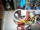
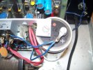
Another thing that i have a question is on the wiring of C301 I want to know if the wiring is connected in the right place to me it seems like it is not. I am including some pictures so that you can tell me if it is or not. I highlighted the positive symbols on the capacitors. Thank you. The print shows one of the capacitors with the positive side to ground.
 

Attachments

  • 100_4602.JPG
    100_4602.JPG
    128 KB · Views: 15
  • 100_4603.JPG
    100_4603.JPG
    120.7 KB · Views: 15
  • 100_4604.JPG
    100_4604.JPG
    175.7 KB · Views: 21
  • 100_4606.JPG
    100_4606.JPG
    97.6 KB · Views: 19
I rechecked the voltages on board PC-37 that previously i had some negative voltages on holes 9 and 19 when they should have been positive voltages and the problem was that i was taken the voltages on the wrong side of the board and the voltages are the correct negative voltages that they should be.
Another thing that i have a question is on the wiring of C301 I want to know if the wiring is connected in the right place to me it seems like it is not. I am including some pictures so that you can tell me if it is or not. I highlighted the positive symbols on the capacitors. Thank you. The print shows one of the capacitors with the positive side to ground.
Those caps should be reversed according to the schematic. Notice the postive signal is not in the same place on the schematic.
 
Last edited:
Back
Top Bottom