• The move to the new server is done. There are some software and database maintenance updates in process. This has us passing the hat around to help out. We appreciate any donations. Seriously, even a dollar helps. The payment page may be found here - https://www.audiokarma.org/support.html

dynaco ST-70 w/ou bias sets

HowlerMonkey

Active Member
I have this great ST-70 that i bought from a fellow Ak'er.
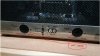
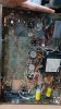
It is a very clean kit with the only "non standard" difference that the front sockets to check the bias have not been wired. I am debating if i have the skills to wire them myself (i might need step by step instructions like the ones you will give a 12 y/o kid to make an omelette - lol)

or if I should buy a dual bias tester (costs $50-$100) that can used directly to the tube sockets?
Any other suggestions that would make this easy so I can check bias every 6 months or so?
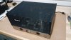
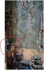
dynaco 00.jpg

dynaco 1.jpg

dynaco 0.jpg

dynaco 2.jpg

dynaco 3.jpg
 
Register to hide this ad
Download an ST70 manual here:

https://hafler.com/pdf/dynaco/Dyna-ST70.pdf

and look at the last page, the wiring diagram. There's a wire from pin 8 of V6 to pin 8 of the right test socket, and a wire from pin 1 of V3 to pin 8 of the left test socket. That's all you need to add. Then connect red voltmeter probe to pin 8 of each test socket and the black probe to the chassis, and set for 1.56 volts. That's all you need to do.
 
Download an ST70 manual here:

https://hafler.com/pdf/dynaco/Dyna-ST70.pdf

and look at the last page, the wiring diagram. There's a wire from pin 8 of V6 to pin 8 of the right test socket, and a wire from pin 1 of V3 to pin 8 of the left test socket. That's all you need to add. Then connect red voltmeter probe to pin 8 of each test socket and the black probe to the chassis, and set for 1.56 volts. That's all you need to do.
Totally correct.
Using adapters that demands tubes to be removed and reseated is bad and the dynaco way
is MUCH better. You only have to solder one wire per side !
 
Download an ST70 manual here:

https://hafler.com/pdf/dynaco/Dyna-ST70.pdf

and look at the last page, the wiring diagram. There's a wire from pin 8 of V6 to pin 8 of the right test socket, and a wire from pin 1 of V3 to pin 8 of the left test socket. That's all you need to add. Then connect red voltmeter probe to pin 8 of each test socket and the black probe to the chassis, and set for 1.56 volts. That's all you need to do.

awesome thanks for the explanation and manual reference. It sounds pretty straightforward...it just looked intimidating when i opened the bottom cover.:eek:
I might give it a try this weekend.
 
As said in another thread , it's only one wire that is needed to complete the biaset.
Being able to read the bias whenever you like without turning off or/and removing
tubes is not a big feature it's "the best way"
 
As said in another thread , it's only one wire that is needed to complete the biaset.
Being able to read the bias whenever you like without turning off or/and removing
tubes is not a big feature it's "the best way"

thanks for the info that makes sense. I have not read the complete manual of the ST-70 but a question comes to mind....if only 1 wire lead is used for bias setting what was the point of the complete front sockets in the original kit then? were the sockets used for optional equipment or something?
 
Since this is something you have to add I'd be tempted to install a 1 ohm resistor on each output tube cathode to ground and run a wire from each tube to the socket in front. Then you can easily measure the current draw on each tube instead of a pair.
 
Kind of rare Stereo 70. It's a later production unit with the green epoxy PCB. 1970s vintage. It might possibly even be a 1980s reproduction by Stereo Cost Cutters who later became Sound Values and Sound Valves.

yes when i bought it it was presented as a late production ST-70, and mentioned that late production ST-70s had improved chassis and PCBs compared to earlier models.
It looked very clean to me and other than the bias sockets not been wired I though it was a good match for what i was looking for = a trouble free tube amp.
I has all original tubes also ...(it had a note from the builder to his friend...lol)

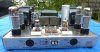
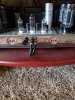
Dynaco ST-70 Front No Cvr.jpg

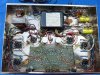
Dynaco ST-70 Bottom Open 1.jpg

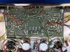
ST-70 PCB Bottom 1.jpg
 
It is a pretty tight space between the front sockets and PCB. Originally I soldered the wire to the front socket first before installing it. It doesn't matter what pin on those sockets you wire too. You can, if you want, solder it to the easiest socket pin you can reach. I got tired of squinting to find the right hole when testing, so I made my own test sockets. Mine has two per side due to the PCB im using lets you adjust and bias each tube separately. So I have two per side. Its pretty easy and cheap to make.
20201019_140201.jpg
 
The bias pots are date coded, 1973, week 38.
Amazing that 1973 denotes a 'newer' model. These amps are still so user-friendly and up to date, except for the scarce 7199 tubes. Butin 73, when I was a first year college student, these would have looked really old fashioned. Dylan had a point with, 'But I was so much older then, I'm younger than that now.'

+1 for the admiration for this amp. Just complete that bias wiring and it looks good to go. You may never need to do any more to it.
 
Thank you all for the great tips and information. I will study the manual and all the information provided and promise to work on this after i have done my due diligence.
No Friday night, after beers project. More like a Saturday morning after coffee :)
 
Last edited:
Thank you all for the great tips and information. I will study the manual and all the information provided and promise to work on this after i have done my due diligence.
No Friday night, after beers project. More like a Saturday morning after coffee :)
Everyone gone for awhile helps too. Nothing like getting interrupted just when you have something figured out and ready to start. :D
 
I have this great ST-70 that i bought from a fellow Ak'er.
It is a very clean kit with the only "non standard" difference that the front sockets to check the bias have not been wired. I am debating if i have the skills to wire them myself (i might need step by step instructions like the ones you will give a 12 y/o kid to make an omelette - lol)

or if I should buy a dual bias tester (costs $50-$100) that can used directly to the tube sockets?
Any other suggestions that would make this easy so I can check bias every 6 months or so?

View attachment 2011738

View attachment 2011739

View attachment 2011740

View attachment 2011741

View attachment 2011742

No kidding this is a very clean kit. :thumbsup:

minion - kissing.gif
 
Totally correct.
Using adapters that demands tubes to be removed and reseated is bad and the dynaco way
is MUCH better. You only have to solder one wire per side !

That is a NICE Stereo 70!

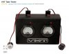
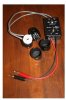
My experience with attempting to adjust the bias settings (on a pair of Ampex EL34 monoblocks) using a unit similar to the one shown below was that the amplifiers became unstable and could be triggered into oscillation. Same both amplifiers.

You're much better off to set the bias current at Dynaco's recommended 50mA each by measuring the "bias set" voltage across the common cathode resistor. Dynaco chose to use a 15.6 ohm cathode resistor so as to provide a 1.56V bias set voltage -- which is the voltage you would get by measuring the voltage of a single cell carbon zinc battery. That way rather than relying on the absolute accuracy of an analog voltmeter of the time, it was only necessary to compare the measured value to that measured from a carbon zinc battery.

By placing a single cell carbon zinc battery in series with the meter with reversed polarity, the meter would read 0V when the bias set voltage is at 1.56V. Doing this will allow you to set the meter scale to the millivolt range which will allow for a more accurate bias setting.


index.php
 
Last edited:
agreed with just wiring up the socket. Its very simple to do and makes the whole bias checking and adjusting process very easy. I have added a functional equivalent to many amps that came with nothing.
 
agreed with just wiring up the socket. Its very simple to do and makes the whole bias checking and adjusting process very easy. I have added a functional equivalent to many amps that came with nothing.

In my opinion, this will also help resale value.
 
Last edited:
Back
Top Bottom