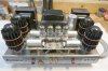
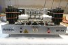
Hi to you Dynaco owners. A few years ago I purchased a ST-70 which has been highly modified by "Lovan". I have used it intermittently but it has been idle for a few months while I listened to my MC-40's. Today, I thought I would put it back "on line" and try it with a recently acquired Van Alstine Model 1 pre-amplifier. I powered it up on my variac and instantly noticed excessive current draw and some "smoke where you hurt" coming from the PC board under the chassis. Cutting to the chase, I have never heard of mods by "Lovan" and would like to get some information and schematic for the mods so I can troubleshoot the problem. Can anyone give me a hand? Thanks in advance. I have attached some pics of the amp.. You can respond here or my email is: nollkamper47@hotmail.com


You are using an out of date browser. It may not display this or other websites correctly.
You should upgrade or use an alternative browser.
You should upgrade or use an alternative browser.
Register to hide this ad

This highlights the problems with customizing. Unless proper documentations
is obtained the device will continue to exist in a non-serviceable state.
In this case i would have teared it down and rebuilt it as per the dynaco manual. Or sell it
as parts ( the transformers are the only really valuable things here )
is obtained the device will continue to exist in a non-serviceable state.
In this case i would have teared it down and rebuilt it as per the dynaco manual. Or sell it
as parts ( the transformers are the only really valuable things here )

https://www.curcioaudio.com/st7des_3.htm
It looks like the Curcio driver board using four 6DJ8's.
Hope this helps
It looks like the Curcio driver board using four 6DJ8's.
Hope this helps


I'm a lot less anti-modification, but lack of documentation can be an issue. Then again half the things in my life have no documentation so to me its more of an annoyance than a real problem. There are only so many ways to make an amp work. This one appears to use 4x 6DJ8 so fair guess the basic circuit is the same as something else. If nothing shows up for a 4x 6dj8, probably something exists using four twin triodes of different types that is the same basic topology. Offhand I'll guess Mullard type driver, but with the input tube wired as a cascode rather than using a pentode. Two triodes wired in cascode acts like a pentode.
Not going to tell you I like it cosmetically or physically though. Having that board sitting way above the chassis like that seems wrong to me. Think I might take some measurements and see if it would be possible to bottom mount some of the components in order to get enough clearance to fit the board in from the bottom like the stock one.
Not going to tell you I like it cosmetically or physically though. Having that board sitting way above the chassis like that seems wrong to me. Think I might take some measurements and see if it would be possible to bottom mount some of the components in order to get enough clearance to fit the board in from the bottom like the stock one.

You were absolutely right on! It turns out that it is the Curcio power supply board and the driver board. I downloaded the schematic and R3 on the p/s board is the failed resistor. Now, to find out the cause. It would be nice to have the parts list on the board but I couldn't find it at that site. I'll see if I can contact them and get the info., assuming that they're still in business. Thanks again for your help heyraz. I'll keep you all posted on my progress. Any additional advice is always welcome.https://www.curcioaudio.com/st7des_3.htm
It looks like the Curcio driver board using four 6DJ8's.
Hope this helps
https://www.curcioaudio.com/st7des_3.htm
It looks like the Curcio driver board using four 6DJ8's.
Hope this helps
That does look like it was made using the Curcio amp kit featured in Volume 1/1989 of Glass Audio magazine.
It takes an old guy to remember it.
The Glass Audio article has compete information including circuit diagrams.
I built one back then and it still resides in a dark corner of my basement.
The complete kit included a complicated regulated power supply contained on the lower circuit board housed inside the chassis.
There's no room inside for the topside board.
The tube coolers and window dressing on top were not part of the kit.
To my ears, the circuitry was way more complicated than needed, to achieve the end result.
schematic
paregsch.gif (887×482) (curcioaudio.com)
I'm assuming "b" here is rectified HV DC. "a" seems to be output from the rectifier, guessing that goes to the filter, maybe from first cap to second via a choke, and back in on "b" ?
Assuming that is not completely wrong, R3 appears to be part of a voltage divider that sets base voltage at Q1. The other half is the zener diode DZ1. That should lock the base voltage for Q1 to whatever the zener voltage is. Looks like Q1 controls Q2 which controls IC1 to produce your regulated output voltage.
If R3 smoked, I'd suspect a bad zener diode and maybe those transistors.
related, this is the driver board portion
padvrsch.gif (611×650) (curcioaudio.com)
not what I thought exactly. Cascode input, but the input is also part of a long tail pair that involves a second cascode setup? Why?
paregsch.gif (887×482) (curcioaudio.com)
I'm assuming "b" here is rectified HV DC. "a" seems to be output from the rectifier, guessing that goes to the filter, maybe from first cap to second via a choke, and back in on "b" ?
Assuming that is not completely wrong, R3 appears to be part of a voltage divider that sets base voltage at Q1. The other half is the zener diode DZ1. That should lock the base voltage for Q1 to whatever the zener voltage is. Looks like Q1 controls Q2 which controls IC1 to produce your regulated output voltage.
If R3 smoked, I'd suspect a bad zener diode and maybe those transistors.
related, this is the driver board portion
padvrsch.gif (611×650) (curcioaudio.com)
not what I thought exactly. Cascode input, but the input is also part of a long tail pair that involves a second cascode setup? Why?

What's up with those heatsinks (?) around the output tubes? Unless I'm mistaken, don't tubes want to radiate their heat into the surroundings rather than have it absorbed and reflected back by pieces of metal stuck to the outside? It's not like the glass envelope needs to be cooled, and those certainly aren't cooling the plates, so...
Maybe the parts list from the Glass Audio article will help:You were absolutely right on! It turns out that it is the Curcio power supply board and the driver board. I downloaded the schematic and R3 on the p/s board is the failed resistor. Now, to find out the cause. It would be nice to have the parts list on the board but I couldn't find it at that site. I'll see if I can contact them and get the info., assuming that they're still in business. Thanks again for your help heyraz. I'll keep you all posted on my progress. Any additional advice is always welcome.

What's up with those heatsinks (?) around the output tubes? Unless I'm mistaken, don't tubes want to radiate their heat into the surroundings rather than have it absorbed and reflected back by pieces of metal stuck to the outside? It's not like the glass envelope needs to be cooled, and those certainly aren't cooling the plates, so...
I recall a lengthy debate about "Pearl Tube Coolers" and similar devices. Some claim they extend the life of the tube, others that they actually reduce it.

Primotubes
Active Member
Re. Pearl tube coolers. My MFA M75 mono blocks were fitted with them but the coolers were retro fitted with a ground wire. Otherwise the coolers being metal can pick up signals like an antenna. This mod worked since lifting the ground would make audible a very low level static. But they definitely help in radiating heat since they got very hot on the kt88 output tubes.I recall a lengthy debate about "Pearl Tube Coolers" and similar devices. Some claim they extend the life of the tube, others that they actually reduce it.
Primotubes
Active Member
Hi, rather than trouble shoot the Curcio mod board you could desolder the original dynaco wiring and install a new board. If i am not mistaken, i think the Curcio mod was first released in the 1980s. It maybe easier to replace with a currently available circuit board than trying to find the replacement parts. Good luck.Hi to you Dynaco owners. A few years ago I purchased a ST-70 which has been highly modified by "Lovan". I have used it intermittently but it has been idle for a few months while I listened to my MC-40's. Today, I thought I would put it back "on line" and try it with a recently acquired Van Alstine Model 1 pre-amplifier. I powered it up on my variac and instantly noticed excessive current draw and some "smoke where you hurt" coming from the PC board under the chassis. Cutting to the chase, I have never heard of mods by "Lovan" and would like to get some information and schematic for the mods so I can troubleshoot the problem. Can anyone give me a hand? Thanks in advance. I have attached some pics of the amp.. You can respond here or my email is: nollkamper47@hotmail.com
I mean, the fact they get hot doesn't mean they're helping. That could be heat that would've been radiated out into the room and is now getting absorbed right up against the tube. I'd love to do some tube dissipation tests with these things -- I'd wager $100 that they reduce the maximum safe dissipation of a tube rather than increasing it. At least their dark matte finish should help lessen reflection of heat back into the tube. But anyways, not really on topic, so I'll leave it be.
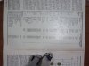
Here's the schematic of the power supply board. The resistor that sacrificed itself is R3 as indicated by the pencil point. It's a 5 watt wire wound.Please post the schematic
Attachments
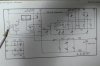
Thanks. I printed it and it will help a lot. I had a tough time reading the print where the reflection covered part of it, but most is OK...thanks for your help.
Hi again. I'm sorry to have dropped the thread here. I spent an unanticipated week in the hospital and haven't been able to get to the computer. I have noted the comments that all of you have made and will do some checking on the two transistors and the zener diode in the circuit. As you can see by the photo, it will take some maneuvering to get one of the boards loose so the components can be removed. I'll keep you posted and thanks again.