• The move to the new server is done. There are some software and database maintenance updates in process. This has us passing the hat around to help out. We appreciate any donations. Seriously, even a dollar helps. The payment page may be found here - https://www.audiokarma.org/support.html

Dynaco ST-70 with Triode USA driver board problem

hogwylde09

Vintage Tube Hi-Fi Rules
Subscriber
I have upgraded one of my ST-70 with the Triode USA EF86 board. First mistake!
The Triode page says it comes with 20 page installation manual LIES! No manual with board and parts.
I now know I should have used the Tubes4hifi high gain 12AU7 board. There is tons of info and Bob
Latino gets involved personally with questions.
I have tried to contact Triode with no results. I received wrong value and also wattage resistors.
I have that corrected by buying my own parts. Also note that eyelets 8, 9 & 10 are unmarked, but I traced
the foil enough to see 8, 9 and 10 are all board grounds. So I have pin 9 to the ground lug near the quad cap,
Pin 8, 10 ohm ground isolation resistor to pin 3 front left takeoff socket (which is an open lug)
Pin 10, 10 ohm ground isolation resistor to pin 3 front right takeoff socket (also an open lug)
The rest of the parts I bought directly from Dynakit Parts which include
new 30/20/20/20 quad cap with new carbon comp 3 watt resistors VOLTAGES DEAD ON SPECS
new bias supply rebuild kit NEGATIVE BIAS VOLTAGE DEAD ON SPECS
on/off and stereo/mono switches
gold plated wider spaced 1/4 phono. input jacks with new metal film resistors
I installed a CL-90 current inrush limiter from Mouser
New choke that I opted not to use on this unit...saving it for my other. The stock one has no leakage and
ohms out fine. I bought double of everything to recap my working ST-70 with an old EF86 board,
Roy Mottram, I believe it has been identified as, from it's yellowish/green color. And it sounds great.
I did the yellow sheet mod with UL fast recovery diodes and bypassed the Selenium with a 1N4007.

HERE IS MY PROBLEM, as per Triodes ONLINE assy. instructions to use the 12AU7, you are supposed to
jumper the board J1 to J2, which I have done, and used eyelets 24 & 25 for filament voltage from the front
power takeoff sockets. I have filament voltage present on both EF86. However I believe (I put it on the back burner) with the associated problem and other projects, if memory serves me correctly, I have filament voltage
to the 12AU7 pins 4 and 5 but the tube heaters will not light the tube, because of what I believe to be missing
heater center tap at pin 9.
As stated above ALL voltages are correct, including bias, ALL tubes light EXCEPT the 12AU7 phase inverter,
and I have MANY 12AU7, all tested with my Sencore Continental II MU150.
I did see another post, with a similar problem, once while doing a search here on Audiokarma, but can't seem to find it again.
Any help with this would be greatly appreciated.
 
Register to hide this ad
12au7(ecc82) has the filament connected as follows :
when using 6.3V AC then connect one side to pin 9 and the other side to 4 and 5 ( yes 4 and 5 should
be connected together. I assume you have 6.3V filament from yout ST70 transformer.

EF86 uses the "classical" filement connection 4 and 5 and want's 6.3V
 
What he said. 4 and 5 normally are connected together to one side of the heater line, 9 to the other. Feed 6 volts across 4 and 5 and the 12au7 is probably not going to do much of anything.

You'd have to chase out the wiring on the socket to those pins to figure out what the appropriate jumper and wiring arrangement is. Unfortunately without a schematic or instructions you sort of have to wing it.
 
I have upgraded one of my ST-70 with the Triode USA EF86 board. First mistake!
The Triode page says it comes with 20 page installation manual LIES! No manual with board and parts

HERE IS MY PROBLEM, as per Triodes ONLINE assy. instructions to use the 12AU7, you are supposed to
jumper the board J1 to J2, which I have done, and used eyelets 24 & 25 for filament voltage from the front
power takeoff sockets. .

Did they or didn't they provide instructions?
 
No they didn't. Only a link online.
And the online troubleshooting section
has nothing thar applies to my problem.
When I get through with some of my outdoor projects, the water from Harvey, has caused erosion and a huge oak down. Then I will get back and make this thing work. OR SCRAP this Triode board and get the tubes4hifi.
 
Whats the tube layout, 12AU7 in the middle, EF86 left and right?

If so, it looks like 1L and 6L go to pins 4 and 5 of the 12AU7 (I may be reading that wrong) and pin 9 is already connected to one side of the heater string. A jumper between 1L and 6L should get you going. It looks like one side of the heater string goes to pin 9, and the other only to pin 4. I'd expect half of the 12au7 to be lit if this is the case.

Assuming of course that twisted pair from the front octal socket is tied to the heater string. I'm just making a guess about that based on what the original design did.
 
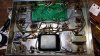
gadget73, that is a problem then, because 1L and 6L is actually reading upside down from the top side of the board. It is actually J1 and J2 which according to the online affair they call a manual,
those are the strap point (which I do have a jumper wire soldered in place) The other option is to leave the J1 J2 un jumped for use of 6CG7, 6922, 7308 or 6DJ8. (you would make the filament connection for them here). Yes the center tube is the 12AU7 phase inverter. The author says to ignore eyelet 24 and 24 for the 6DJ8 and variants, and use J1-J2 for filament connections. Also, you are correct the twisted pair from the front takeoff sockets are the 6.3 ac heaters. So, While Triode does not answer tech calls NOR return emails. I WOULD AVOID THEM LIKE THE PLAGUE.
The author of the material is Matt Inhen http://site.triodestore.com/New_ST70_Driver_Board.pdf
 

Attachments

  • 069.jpg
    069.jpg
    105.8 KB · Views: 14
ok, so the heater is wired to pin 9 on one side and pins 4+5 on the other. The 12AU7 still does not light? Can you confirm that you have 6.3 vac at the proper pins? Just wondering if its a broken wire somewhere in the heater string and not actually a connection problem on the board. Also its worth confirming that you do indeed have heater voltage at those front sockets. If the wiring has been unhooked from there, its not going to work.
 
Well, I got it figured out. I studied the board traces and found my error, I had omitted the pair twisted filament wires that come from the front octal sockets to eyelets 24 and 25. Amp up and running.
The author that wrote the assembly instruction's were vague at best. He also has the 9 pin tube voltage troubleshooting chart all wrong. Thanks for pointing me in the right direction, gadget73.
 
The Dynakit PASS, I am using is all stock, it and the tuner were given to me by my son. I finished at around midnight, so didn't have a lot of time to really give it the ultimate sound check. But with miss matched EL34's, Ruby 12AU7, Russian CP GZ34 and a used pair of Valvo EF86, (one tests low) It sounds darn good with a cheap CD player hooked up. I have the big bottle Sylvania 6CA7 dual top halo disc getters, tests as good as new (came in it), a ANOS Mullard 12AU7, and matched NOS mesh plate Valvo labeled Mullard EF86, It is just going to get better. No complaints! Oh and going to move it all to the master bedroom, in place of my Marantz 2252b, vintage Akai SW-155 and Pioneer HP60's.
I am going to rebuild and mod the PASS and FM3 tuner next. But going to listen for a while first.
Will be using the JBL L200t3's and Klipsch Kg 5.5's
 
EF86's are kind of touchy. I have a couple of them, two are horribly noisy and microphonic, the other two are dead silent and in excellent functional shape. No idea if its use or what, the noisy ones are Amperex, the others are some other Phillips production. I know the good ones are mesh plate, honestly I can't recall what the noisy ones are.
 
I bought my first ST70, with mods already done. Looks like they had been done years ago. It has the original Xf4 Mullards, Amperex labeled Mullard EF86, they flash on start, a Bugle boy 12AU7. Had a 5U4G in it, broke it, pulled the 6CA7's to test them when I went to look to purchase it. At least I didn't break a vintage Mullard.They were so tight in the sockets. But to the point, it had a early Curio board, taller power transformer with cloth wire, bias test pin jacks in place of the octal power take offs. I don't know about the inside, I've never opened it up. The seller didn't even know what it was, other than he wanted $450.00 for it. That us when I knew I loved the pentode 1st gain stage tubes.
My son also builds hand wired boutique guitar amps. So we already were getting into 6AK5's EF86 and still using some 12AX7 triode in some circuits. Give us an old Hammond Organ power tranny, and throw out the rest. Everything else from chassis to hand staked turret boards comes from Hoffman Amps, Mouser, Antique Radio Supply, Sourmoush Cabs and anywhere we can source low wattage Celestine speakers.
 
I kind of like pentode inputs, not everyone does. I find they have a little more on the top end, but done wrong it can make for shrill annoying highs. The stock original Dynaco circuit used a pentode front end with a triode driver. You're basically back to near the stock design, just using a different combination of tubes to get it done. I have a little German console amp with a fairly similar setup, EF86 and I forget what the cute little triode tube is but its effectively half a 12AT7, again not too different than Dynaco was doing with the 7199 tube. It also sounds very nice.
 
I found the schematic I drew for it, EC92. Google says thats the same as 6AB4. Seems I need to re-draw that schematic. I have the original as-built one, and a reworked driver stage, but I never drew up a complete one that actually has the whole complete working unit.
 
gadget73, that is a problem then, because 1L and 6L is actually reading upside down from the top side of the board. It is actually J1 and J2 which according to the online affair they call a manual,
those are the strap point (which I do have a jumper wire soldered in place) The other option is to leave the J1 J2 un jumped for use of 6CG7, 6922, 7308 or 6DJ8. (you would make the filament connection for them here). Yes the center tube is the 12AU7 phase inverter. The author says to ignore eyelet 24 and 24 for the 6DJ8 and variants, and use J1-J2 for filament connections. Also, you are correct the twisted pair from the front takeoff sockets are the 6.3 ac heaters. So, While Triode does not answer tech calls NOR return emails. I WOULD AVOID THEM LIKE THE PLAGUE.
The author of the material is Matt Inhen http://site.triodestore.com/New_ST70_Driver_Board.pdf
Just finished the Triode ef86 board today on my st 70, wired for a 7308 phase splitter. Was suprised by the voltage chart also. I have way more voltage than the chart suggests. Waiting on the ef86 tubes to try it out.
 
Back
Top Bottom