• The move to the new server is done. There are some software and database maintenance updates in process. This has us passing the hat around to help out. We appreciate any donations. Seriously, even a dollar helps. The payment page may be found here - https://www.audiokarma.org/support.html

Dynaco ST70 Mystery Modification

FireGuruMN

Active Member
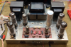
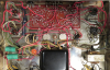
I recently acquired (finally) a Dynaco ST70 for a reasonable expenditure. I intend to do the obvious things like replace defective caps and clean the pots. And replace the ORIGINAL Dynaco output tubes. But after cleaning out the spider webs I found some unwelcomed modifications. Here is a picture of the insides:
upload_2019-5-30_19-45-49.png
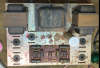
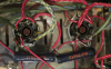
What are those two large resistors on the left hand side. When I meter them (in circuit) they read about 16 ohms. If there was just one then it would seem to be a replacement for the original 15.6 ohm resistor. But what is the other one doing? Here is a close up:
upload_2019-5-30_19-48-27.png
I have a replacement 15.6 ohm resistor so do I just pull these out, install the replacement in the correct location and move on? Or is the person that put two resistors in the circuit smarter than me in some way?

At some point I believe this was used as a guitar amplifier if that provides a clue to the mystery.

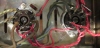
Here is a picture of the other side of the output tube sockets if that is of any value:
upload_2019-5-30_19-51-41.png

Hoping for a rainy weekend so I can dig into this. . .I have a used MBT PACE commercial soldering station off CL that I am dying to try out. What a beast.
 
Register to hide this ad
Thanks for the thorough and quick reply.:thumbsup:
The 7199 tubes are original Dynaco and probably still good. I have a replacement set if needed. Only two of the output tubes are original Dynaco. They are on the "modified" side. The "getter" is totally gone on one of them. I don't have much hope for it. The other might still test ok. The other side of output tubes are Sylvania. They are not pretty either. I will run them all though a tube "checker" (Heathkit TC2). I don't have a full on tube tester that works. The rectifier might be RCA, it is not clearly printed any longer. I'm mostly looking at a nice chassis, cage, circuit board and hopefully good iron. I am not far enough into this to know. Thanks for the advice on not spraying the pots. I heard disaster stories of people spraying carbon pots and all the carbon disappearing. I'll check all the resistor values of course. I have boxes of old school carbon resistors that I got from a repair tech so I can keep the original look if I have to replace any. I ordered matched quad of "reissue" Russian Mullard tubes. I didn't spring for Gold Lions. Man are those pricy tubes. I will put the original Dynaco tubes on the eye-candy display with Fishers, Harman/Kardon and Telefunken's. :biggrin:

I did order some 15.6 resistors and other bits from the dynakit site. I was impressed by the Dynakit site. Nice to see you can still buy do-it-yourself kits. I tore down a pair of W5M's last year and rebuilt them from the manual to relive childhood memories of building Heathkits with my Dad. They were so heavily modified/burned out it was probably the best thing to do with them. I do wish I had replaced the tube sockets though. I still have to do the WAP2's. :blah:

Any thoughts on adding a thermistor to the power input? What about a grounded power cable? The original power cord is pretty crispy so it has to go no matter what.
 
As others has already answered the questions i only add that replacement of an old power cable is
a safety issue and should be done!
Using a 3 wired connected to a grounded outlet enhances safety, and if other equip also is grounded
it will reduce hum as no current needs to flow in the signal cables.
Myself mounts a IEC inlet wherever i can , this will simplify power cable replacement and avoid the
"knot-on-cable" mounting of a power cable.
 
Back on the bench now after a nice Fall.
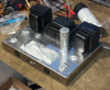
My tubes, capacitors and other bits were sitting in a box all summer but I was too busy out side to work. Here is the pretty side:
upload_2019-11-29_17-31-28.png
and the business end:
upload_2019-11-29_17-34-17.png
There is not much to say about these amps that has not been said. Here is what I did:
  • Replaced the power cord (bought a 16 gage extension 6 foot cord from Menards and cut the female end off. Nice pliable cords)
  • Replace the electrolytic cap.
  • Added a CL80 thermistor
  • Replaced the multi-cap can with one from dynakit.
  • Replace the black caps on the PC board with Solen caps. I used qty 4 of 0.22uf caps and qty 2 of 0.1uf caps. These are larger than the original values but I read somewhere it does not matter in this application. And it does not seem to matter.
  • Replace the precision 15.6 ohm resistors. Earlier I mentioned the mystery modifications that were done to this amp. I reversed those and replace both resistors so they would match. My understanding is that the amp was modified for use as a guitar amp and they wanted it to distort more easily.
  • Some one smarter than me told me to use a Schottky diode to replace the selenium diode for [reasons]. I did and it seems to work but I don't know if I could tell the difference. DIgikey part: IDH03G65C5XKSA2-ND
  • All the resistors on the PCB measured good so I left them alone. They were a little high in most cases but they look nicer that modern ones.
  • Put in all new output tubes and adjusted the bias. I put the ORIGINAL Dynaco labeled tubes on display. Just too cool to burn them out.
  • The original Dynaco 7199's are still working.
I just finished running it for about 4 hours and it sounds wonderful using a Spec-1 preamp and HPM100 speakers. But I have to say a Fisher SA100 I have has smoother bass. Might be the tube selection. Or 1000 other things.

This thing gets HOT. The outside of the cage was reading 150F right above the tubes. No red plating or any nasty things like that.

I have another ST70 that I picked up this summer. Its in rough shape. A true barn find. The barn leaked. I painted the chassis so it is presentable but I might have to order a replacement chassis in the end. It came with an FM tuner and a transistor 4d amp. I also got an SCA35 in the deal so that is up next on the bench. Somewhere in my piles is a PAS3. I'll let you know when I find it. It's going to be a musical winter.
upload_2019-11-29_17-57-5.png
Hope the iron is good on this one.
I saw a diagram on how to bridge the speaker terminals on an ST70 to get 70 watts. So with two of them I could make a lot of noise.
 
Thanks as always for the reply.
  • There are 2 bias capacitors. The lower one is just barely visible.
  • I have ordered the correct value capacitors for the PCB. I will install those in the second amplifier and see how it sounds. Some day I will read through that entire post you quoted. Lots of priceless information buried in there.
  • All of the resistors were within tolerances. It was interesting that all the values were reading high. Seems like that they go up in resistance with age. I will replace the old resistors with NOS carbon resistors in the second amplifier. I have several bins of NOS resistors from a retired stereo repairman. I heard recently that these resistors are a bit of a treasure for vintage restorations. Maybe I will try some metal films at some point also. It is so easy to work on the PCB parts. Until the traces start pulling off. . .
  • Running the amplifier today it sounded better. Maybe the tubes are breaking in? Maybe my memory of the SA100 sound has faded. Either way it is not a night and day difference. They both sound great.
  • Running two amplifiers is more about conspicuous consumption than actual improvement in audio quality. I'm probably not even using much of the 35wpc of a single amplifier.
Even though it will cause much cringing I ended up painting the chassis on the second ST70. The chrome was just too wasted from it's life in a barn. Some day I may order a replacement chassis but that will put me way upside-down on the investment.

Ordering parts for the PAS3x now. . .WAY too much discussion on those restorations.
 
Pictures! I always forget the pictures.
upload_2019-11-30_19-57-0.png
I taped off the sides because they were not too bad and I wanted to keep what was left of the lettering. I think that it will look ok with the cover on. Here is a picture of the original finish and the paint job.
upload_2019-11-30_20-0-27.png
I could only find "chrome" paint. Really it needs to be "nickel chrome" to get the warmer color. But no one ever told me I was too patient. It looked a lot worse the first day but it dried to a much shinier finish. If I had it to do over I would probably have left it alone since it is mostly under the cover.
 
If you want to dry anything out just bring it to Minnesota in the winter!
Seems to me like resistors in a tube amp are getting baked pretty well all the time.
Very interesting that it is the moisture that changes the resistance in the carbon comp resistors. But the topic has my interest now. Time to do some Googling.
 
Back
Top Bottom