• The move to the new server is done. There are some software and database maintenance updates in process. This has us passing the hat around to help out. We appreciate any donations. Seriously, even a dollar helps. The payment page may be found here - https://www.audiokarma.org/support.html

Dynakit ST70 - Unopened and Untouched?

Leviasean15

Active Member
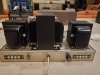
I have been quite fortunate lately and I have found a plethora of wonderful equipment in particularly exceptional shape, including a pair of EV Regency 3's, The Fisher 800b (original tube complement, never seen a soldering iron) and most recently, a Dynakit ST70!

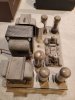
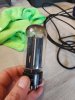
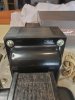
Upon removal of the protective cage, I noticed the absence of any tool markings from inept or speedy technicians on the case, cool! All of the printing is intact and look almost new. Most importantly, staring back at me was the original Dynaco by Mullard tubes, all of them.

The gentleman I purchased the amplifier from was young, in his early 30's and had received it as present and had never bothered with it. I believe his family to be the original owners however. The matching preamp has been misplaced somewhere in one of the family homes, they are looking for it for me to purchase as well.

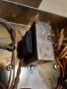
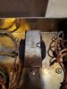
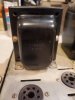
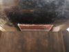
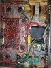
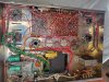
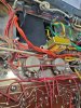
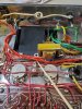
The choke has seen better days, it reminds me of how my mother enjoyed her toast back in the day! I am inferring that this happened to the choke as the amplifier was probably never biased and then it was put in storage.

I do not have a lot of experience yet servicing my own gear, but I am a good study and a quick learner. I am comfortable with a soldering iron and getting better at reading schematics.

Where should I purchase a replacement choke? They are available online from dynakitparts.com but I figured I would ask the almighty AK community before making a move.

Also, aside from the selenium rectifier, is there anything else that I must change to avoid catastrophic failure down the road?

Thank you for taking the time to read, as always, much appreciated! Also, notice how the dust has fallen undisturbed, like snow!
 

Attachments

  • 20210209_193446.jpg
    20210209_193446.jpg
    177.6 KB · Views: 221
  • 20210209_180903.jpg
    20210209_180903.jpg
    80.4 KB · Views: 217
  • 20210209_180943.jpg
    20210209_180943.jpg
    187.7 KB · Views: 219
  • 20210209_180858.jpg
    20210209_180858.jpg
    82.3 KB · Views: 210
  • 20210209_180057.jpg
    20210209_180057.jpg
    114.9 KB · Views: 211
  • 20210209_174941.jpg
    20210209_174941.jpg
    79.3 KB · Views: 206
  • 20210209_174841.jpg
    20210209_174841.jpg
    46.1 KB · Views: 205
  • 20210209_180721.jpg
    20210209_180721.jpg
    152.2 KB · Views: 217
  • 20210209_174239.jpg
    20210209_174239.jpg
    160.3 KB · Views: 213
  • 20210209_172549.jpg
    20210209_172549.jpg
    135 KB · Views: 213
Register to hide this ad
At first glance: power transformer is not the one which came new with a Dyna70
Choke is chocolatey brown, but lots of transformers turn colors and it doesn't necessarily mean they're shot.
Testing will prove that out.
I'd start by bringing it up on a variac to see if the replacement transformer is even close to correct for the amp. Given the inadequacy of the original, you stand a good chance of it being better than new, but you should at least know what you're working with.
I'd start off by replacing all the electrolytic caps and the 4 coupling caps to the output tubes. The bias rectifier can be replaced with modern diodes, and probably should be, but to start out, bring it up slowly on a variac and determine what's actually going on.


Edit:
Print The manual. Its available online, and for a buck or 2 In printing fees it's worth having, on paper, in front of you.
That way you can make notes and have all the information pertaining to this amp in one place, and convenient.
Paper also allows you to make notes using a pencil, about this specific amp, and to file the papers with the amp to show when it was serviced.
Yes, us tube guys like low tech solutions which work.
 
Last edited:
That choke does look a little more charred than usual. Drips are typical but black crispy paper not so much.

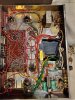
That is a considerably larger power transformer, and it looks like a 5U4 rectifier. Guessing that whatever took out the original transformer is why the choke is crispy looking.

The small transformer bottom side is not original either. Wild guess is that its being used for the bias supply but you'd have to trace the wiring. I can't quite see it.

can definitely say that someone has been in here, but probably not in a long time based on that layer of dust.
 
See if you can get a date code off of the bias pots
Early ones did not have the date code, later ones did

If it has two holes on each side to hold the cage on then it is an early production
Check the date codes on the EL34's
 
At first glance: power transformer is not the one which came new with a Dyna70
Choke is chocolatey brown, but lots of transformers turn colors and it doesn't necessarily mean they're shot.
Testing will prove that out.
I'd start by bringing it up on a variac to see if the replacement transformer is even close to correct for the amp. Given the inadequacy of the original, you stand a good chance of it being better than new, but you should at least know what you're working with.
I'd start off by replacing all the electrolytic caps and the 4 coupling caps to the output tubes. The bias rectifier can be replaced with modern diodes, and probably should be, but to start out, bring it up slowly on a variac and determine what's actually going on.


Edit:
Print The manual. Its available online, and for a buck or 2 In printing fees it's worth having, on paper, in front of you.
That way you can make notes and have all the information pertaining to this amp in one place, and convenient.
Paper also allows you to make notes using a pencil, about this specific amp, and to file the papers with the amp to show when it was serviced.
Yes, us tube guys like low tech solutions which work.
Great advice, I will definitely print the manual and note everything down. I am a big fan of list building and pencil&paper.
 
See if you can get a date code off of the bias pots
Early ones did not have the date code, later ones did

If it has two holes on each side to hold the cage on then it is an early production
Check the date codes on the EL34's
It appears that the bias pots were made the 16th week of 1961.

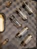
The date codes on the el84's are all the same:
XFI
B0J4
Blackburn, 1960, 4th week of October.

The 7199 made in USA
6l-22
274

Rectifier 5U4GB
838 Japan
06 06N
RTT
 
That choke does look a little more charred than usual. Drips are typical but black crispy paper not so much.

That is a considerably larger power transformer, and it looks like a 5U4 rectifier. Guessing that whatever took out the original transformer is why the choke is crispy looking.

The small transformer bottom side is not original either. Wild guess is that its being used for the bias supply but you'd have to trace the wiring. I can't quite see it.

can definitely say that someone has been in here, but probably not in a long time based on that layer of dust.
Here are some better pictures of the ST70
 

Attachments

  • 20210211_101122.jpg
    20210211_101122.jpg
    113.6 KB · Views: 92
  • 20210211_095803.jpg
    20210211_095803.jpg
    180.7 KB · Views: 86
  • 20210211_095547.jpg
    20210211_095547.jpg
    193 KB · Views: 87
  • 20210211_095425.jpg
    20210211_095425.jpg
    194.9 KB · Views: 82
  • 20210211_095112.jpg
    20210211_095112.jpg
    184.3 KB · Views: 82
  • 20210211_094819.jpg
    20210211_094819.jpg
    98.3 KB · Views: 87
Those Blackburn el34s are what you want.
Same with the 7199s.
5u4 is not the correct rectifier for an original ST70, but may work perfectly with the different transformer it has now.

Perhaps the original builder put a higher current rectifier in it in an attempt to make it actually put out 35 wpc into both channels at the same time. This is only speculation and theres probably no way to know how or why it played out the way it did.
Start it on a variac, there may be little wrong with it.
 
If that new power transformer has a part number on it you will have a more complete picture of what you have and can draw a schematic.
 
The two black wires on the small transformer on the bottom side appear to tie to mains. Looks like one goes to the fuse holder and the other to the terminal strip where the other end of the cord lands. Its the wires on the other side I can't quite chase out. All the red wires sort of blend together.
 
The two black wires on the small transformer on the bottom side appear to tie to mains. Looks like one goes to the fuse holder and the other to the terminal strip where the other end of the cord lands. Its the wires on the other side I can't quite chase out. All the red wires sort of blend together.
The black wires connect to the fuse holder and the on/off switch. The red wire runs to what appears to be a ground, between the two bias pots.
The "ground post" has a second red wire connecting it to a 10 ohm resistor and 50 uF capacitor.

Edit: after more research, the "ground post" is possibly the selenium rectifier.
 

Attachments

  • 20210211_104216.jpg
    20210211_104216.jpg
    154.2 KB · Views: 58
  • 20210211_104346.jpg
    20210211_104346.jpg
    162.9 KB · Views: 57
  • 20210211_104550.jpg
    20210211_104550.jpg
    164.9 KB · Views: 54
  • 20210211_104607.jpg
    20210211_104607.jpg
    135.3 KB · Views: 53
  • 20210211_104646.jpg
    20210211_104646.jpg
    158.7 KB · Views: 53
Last edited:
If that new power transformer has a part number on it you will have a more complete picture of what you have and can draw a schematic.
It is a Hammond transformer:

272JX
Type X 60 Hertz Class A
V.A. 195
115 Volts

The internet says it provides 5.0V for the rectifier and 6.3V for heater filaments.
 

Attachments

  • 20210211_105750.jpg
    20210211_105750.jpg
    54.5 KB · Views: 30
  • 20210211_094819.jpg
    20210211_094819.jpg
    98.3 KB · Views: 29
Screenshot_20210211-080642_Samsung Internet.jpg

600v center tapped, that's a number we can live with.
5v will be required to run any rectifier, but the current rating is the relevant factor. Stock had 2 amps, you get 4. Stock had one 5ar4, you get the option to use 2.
6v at 8 Amps will light the heaters of all the tubes, no problem there.
That hammond has no bias tap or winding, which seems to demystify the other transformers which has been mounted underneath. Its likely providing bias voltage.
 
One wonders about the replacement, the oem xformer is more than adequate with the tube rectifier limitation.
 
The black wires connect to the fuse holder and the on/off switch. The red wire runs to what appears to be a ground, between the two bias pots.
The "ground post" has a second red wire connecting it to a 10 ohm resistor and 50 uF capacitor.

Edit: after more research, the "ground post" is possibly the selenium rectifier.
While tracing the red wire, I noticed one of the resistor leads was disconnected so I re-soldered it.

I also tested the resistance of the choke with a MM and it gave me a reading of 46.7 ohms. I believe it is supposed to be 65 ohms?
 

Attachments

  • 20210211_112317.jpg
    20210211_112317.jpg
    104.4 KB · Views: 25
  • 20210211_113452.jpg
    20210211_113452.jpg
    120.4 KB · Views: 25
The black wires connect to the fuse holder and the on/off switch. The red wire runs to what appears to be a ground, between the two bias pots.
The "ground post" has a second red wire connecting it to a 10 ohm resistor and 50 uF capacitor.

Edit: after more research, the "ground post" is possibly the selenium rectifier.

yeah square thing between the pots is the rectifier. Sounds like the little trafo is the bias supply, which makes sense if the main power transformer has no bias winding.

Possible that resistor on the terminal strip was disconnected for a reason. I'd probably power this with no rectifier tube just to get an idea what the bias supply is doing before trying it with high voltage available. If the add-in trafo has a higher output voltage than the original tap the extra resistor might be needed to bring the voltage down. Or maybe its supposed to be in parallel with the 10k to bring it up. You should get something like -40v at pin 5 of the EL34 socket.
 
That choke does look pretty crispy. Dynakit sells new 62 ohm chokes. It's nothing special, It can be found elsewhere too. Wouldn't a 5AR4/GZ34 rectifier be ok in this one? You would get a softer start.
 
Back
Top Bottom