

You are using an out of date browser. It may not display this or other websites correctly.
You should upgrade or use an alternative browser.
You should upgrade or use an alternative browser.
Early AU-20000 restoration project - oh boy!
- Thread starter w1jim
- Start date

Hipocrates
Super Member
heat can be another option too. I don't know of those like to run hot
But I think rebuild and then start to measure from the power supply to the drivers and outputs section will give you a nice clue.
But I think rebuild and then start to measure from the power supply to the drivers and outputs section will give you a nice clue.

First step - remove the heat sink (which requires desoldering wires) and test the transistors. I found one each PNP and NPN shorted out. I’ll replace all of them with onsemi MJ21193G and MJ21194G.
Also clean and put fresh grease on the mica insulators.
Next I need to figure out how to get to the emitter resistors and check them.
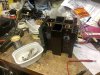

Also clean and put fresh grease on the mica insulators.
Next I need to figure out how to get to the emitter resistors and check them.
Last edited:
Getting at those emitter resistors would require some more desoldering - I managed to reach in there with my probes after removing the screws - fortunately they’re all good.
New onsemi’s are in and ready for reassembly.
No, my work bench isn’t always this neat.


New onsemi’s are in and ready for reassembly.
No, my work bench isn’t always this neat.
Hipocrates
Super Member
Nice, good progress so far


richardpp
Well-Known Member
As you're sooo close to the emitter resistor boards, can I suggest you go ahead, separate the heatsinks, and remove the boards so you get a good look at the solder joints that pass through the board. If any look doubtful under 10x mag they should all be pinned and re-soldered. That is if they haven't already been done.

I seem to remember a long running fault investigation on one of these which would 'blow up' every now and again with no explanation, in a similar manner to how this one has. As far as I can remember the cause was as stated in the quoted post, or was contributory - and is probably a 'must do' for one of these.As you're sooo close to the emitter resistor boards, can I suggest you go ahead, separate the heatsinks, and remove the boards so you get a good look at the solder joints that pass through the board. If any look doubtful under 10x mag they should all be pinned and re-soldered. That is if they haven't already been done.

A timely and well informed post richardpp
(especially if I am correct about the previous case mentioned).
Last edited:
That’s what I was thinking, so I cracked it open last night to solder the pass-through connections.
Prior to that I had it running in my shop when I heard a “pop”. I had heard a pop prior to the previous melt down so I shut it off immediately.
I’m also going to swap out transistors TR04 & TR05 on the driver board just to be safe - I’ve already replaced all the others on that board.

Prior to that I had it running in my shop when I heard a “pop”. I had heard a pop prior to the previous melt down so I shut it off immediately.
I’m also going to swap out transistors TR04 & TR05 on the driver board just to be safe - I’ve already replaced all the others on that board.
Replaced the two transistors on the driver board:
2SA818 (EBC) - 2SA1220 (ECB)
2SC1628 (EBC) - 2SC2690 (ECB)
<Note - corrected part numbers>
The pinout is different so a simple lead crossover is required.
Since the points where the bias reading is accessed is so awkward to get to I make a habit of soldering leads with connectors on the end for safety reasons.
I’ve been playing it for a while - so far no smoke .
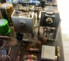
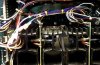
2SA818 (EBC) - 2SA1220 (ECB)
2SC1628 (EBC) - 2SC2690 (ECB)
<Note - corrected part numbers>
The pinout is different so a simple lead crossover is required.
Since the points where the bias reading is accessed is so awkward to get to I make a habit of soldering leads with connectors on the end for safety reasons.
I’ve been playing it for a while - so far no smoke
.
Last edited:

kevzep
Its all about the Music
Replaced the two transistors on the driver board:
2SA818 (EBC) - MJE350G (ECB)
2SC1628 (EBC) - MJE340G (ECB)
The pinout is different so a simple lead crossover is required.
Since the points where the bias reading is accessed is so awkward to get to I make a habit of soldering leads with connectors on the end for safety reasons.
I’ve been playing it for a while - so far no smoke
View attachment 1480442
View attachment 1480445
Those are not very good substitutes. The originals have a transition frequency of 120mhz, the MJE340/350 doesn't even have a published spec for FT, best I can figure is they are around 30mhz.
You'll want to use the KSA1220 and KSC2690 for subs for those particular transistors ...
Thanks for your wisdom Kev.Those are not very good substitutes. The originals have a transition frequency of 120mhz, the MJE340/350 doesn't even have a published spec for FT, best I can figure is they are around 30mhz.
You'll want to use the KSA1220 and KSC2690 for subs for those particular transistors ...
Good thing I keep parts on hand - swapped them out.
kevzep
Its all about the Music
No problem Jim, I've got your back mate!!Thanks for your wisdom Kev.
Good thing I keep parts on hand - swapped them out.
What package were those original transistors? Just looking at the heatsink there, were they TO202 or something? I never looked at that part of the spec.....
Yes, I believe they are TO202 cases - that’s why they had a rectangular spacer.No problem Jim, I've got your back mate!!
What package were those original transistors? Just looking at the heatsink there, were they TO202 or something? I never looked at that part of the spec.....
Rally on!
kevzep
Its all about the Music
Yeah tough to get something like that now, but the KSA and KSC will do a good job!!Yes, I believe they are TO202 cases - that’s why they had a rectangular spacer.
Rally on!
Yes!! Its rally season over here at the moment!!
I’m coming up on two months of good performance on my AU-20000.
Thing is that it seems to running much hotter than I expected - even at low volume levels the top of the amp is at about 130F.
I think I have the bias set properly - but of course I could be wrong.
What could cause it to run hot like this?
Thing is that it seems to running much hotter than I expected - even at low volume levels the top of the amp is at about 130F.
I think I have the bias set properly - but of course I could be wrong.
What could cause it to run hot like this?
A double check of the bias would be a good idea, other than oscillation, I can't think of another reason why it might run so hot - even, as you say 'at low volume levels'.What could cause it to run hot like this?
I assume the heat is mostly coming from the main heatsinks?
Last edited:

Not a good way to do it even if you added 4 fuses, (2 for each channel), but I suspect you might have added 2 fuses? (2 or 4 - a good idea with this amp to protect the transformer).Could I measure current there by pulling the fuses and inserting my amp meter?
With one meter you'll be measuring only the positive rail current, and not the negative rail current (for example). Which in any case will be three times the bias current, (3 x 35mA) as the bias is measured across 1 set of emitter resistors (35mV = 35mA). It is a confusing way to do it as I am not sure how measuring only +ve current (or -ve) will affect the readings.
Also, if it was me I'd want to know what each OP transistor pair was pulling current-wise, especially with the symptoms you seem to have. So, I think measuring across each emitter resistor pair would be the way to tackle this, I am guessing this will be a PIA.
Last edited: