


ecluser
Super Member
The objective of this thread is to provide an easy way to test Darlington power output packs before installation in an amplifier. Full characterization like maximum power, THD, is not the object of this thread. It is rather a simple test with minimal tools to check if a power pack is operational or defective. I will take the STK-0029 to illustrate the procedure, but it is not limited to that particular model. The reader should refer to the datasheet of his particular power pack. Here is the equivalent circuit of the STK-0029
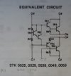
In most amplifiers, pin 10 will be connected to a current source of the order of 6 or 7 mA, pin 1 will be connected to the collector of a transistor that will provide all the voltage gain of the amplifier. Pin 9 will be connected to the positive power supply, pin 2 will be connected to the negative power supply. In some amplifiers there will be two emitter resistors connected in series between pin 8 and pin 3. The junction between those emitter resistors will be connected to the output of the amplifier. In some amplifiers pin 8 and pin 3 are simply connected together, without emitter resistors.
The first thing to check is possible short circuit between pins 9 and 8, between pins 3 and 2, between pins 9 and 10, and between pins 1 and 2. If emitter resistors are built into the power pack, like the STK-1050 and the Sanken ones, check those emitter resistors to see if they are open.
The testing procedure explained here involves only one low voltage DC power supply. It could be a battery for a portable power tool if you don't have a variable power supply. Unless the power pack is properly mounted on a large heat sink, it is preferable to keep the supply voltage low. Here is the complete circuit for testing the power pack
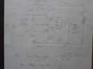
As you can see two emitter resistors were connected between pins 8 and 3, because they are not implemented into the STK-0029. Two bias resistors were connected between the power supply and the input pins. Since those resistors have the same value, the output of the amplifier will set itself at 50% of the supply voltage, in the absence of a load at the output. Of course, if there is an appreciable current into a load at the output there will be a voltage drop in Re1 and the output voltage will be less than 50% of the supply voltage. The value of those resistors need to be computed according to the voltage of the power supply in order to have approximately 5mA of bias current in the input stage. Although the bias voltage source (sometimes called a bias spreader) is a variant of the Vbe multiplier, the voltage between the In+ and In- pins is not totally invariable in regard to variations of the bias current in that stage. It is particularly true for the Sanken power packs, in which the bias stage is made with diodes and a resistor. If Rb1 and Rb2 are too small, there will be too much bias current in the output transistors. Before connecting the load at the output, measure the voltage drop in the emitter resistors and compute the bias current in the output transistors. The complete set-up looks like this
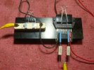
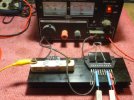
Connexions to the STK pins were made with female Molex contact pins. It is convenient if you have more than one power pack to test. Here, the STK was affixed to an heat sink with a large paper clip.
In most amplifiers, pin 10 will be connected to a current source of the order of 6 or 7 mA, pin 1 will be connected to the collector of a transistor that will provide all the voltage gain of the amplifier. Pin 9 will be connected to the positive power supply, pin 2 will be connected to the negative power supply. In some amplifiers there will be two emitter resistors connected in series between pin 8 and pin 3. The junction between those emitter resistors will be connected to the output of the amplifier. In some amplifiers pin 8 and pin 3 are simply connected together, without emitter resistors.
The first thing to check is possible short circuit between pins 9 and 8, between pins 3 and 2, between pins 9 and 10, and between pins 1 and 2. If emitter resistors are built into the power pack, like the STK-1050 and the Sanken ones, check those emitter resistors to see if they are open.
The testing procedure explained here involves only one low voltage DC power supply. It could be a battery for a portable power tool if you don't have a variable power supply. Unless the power pack is properly mounted on a large heat sink, it is preferable to keep the supply voltage low. Here is the complete circuit for testing the power pack
As you can see two emitter resistors were connected between pins 8 and 3, because they are not implemented into the STK-0029. Two bias resistors were connected between the power supply and the input pins. Since those resistors have the same value, the output of the amplifier will set itself at 50% of the supply voltage, in the absence of a load at the output. Of course, if there is an appreciable current into a load at the output there will be a voltage drop in Re1 and the output voltage will be less than 50% of the supply voltage. The value of those resistors need to be computed according to the voltage of the power supply in order to have approximately 5mA of bias current in the input stage. Although the bias voltage source (sometimes called a bias spreader) is a variant of the Vbe multiplier, the voltage between the In+ and In- pins is not totally invariable in regard to variations of the bias current in that stage. It is particularly true for the Sanken power packs, in which the bias stage is made with diodes and a resistor. If Rb1 and Rb2 are too small, there will be too much bias current in the output transistors. Before connecting the load at the output, measure the voltage drop in the emitter resistors and compute the bias current in the output transistors. The complete set-up looks like this
Connexions to the STK pins were made with female Molex contact pins. It is convenient if you have more than one power pack to test. Here, the STK was affixed to an heat sink with a large paper clip.


