

You are using an out of date browser. It may not display this or other websites correctly.
You should upgrade or use an alternative browser.
You should upgrade or use an alternative browser.
Eico Classic 2050 - sat idle for 3 decades
- Thread starter lqpete11
- Start date

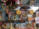
I have replacement PEC module PC Boards on order, but I didn’t know the coupling caps were in them. What are the four 0.1 uf 400 VDC caps in the pic below?If the grid bias voltage DC is increasing as temp rises I think you need new coupling caps which will be a pain in this amp since they are embedded in the PEC modules.
Attachments
Last edited:

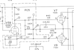
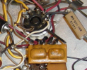
The schematic definately shows the output 0.027uF coupling caps in the PC5 PEC's. One of the pin 6 from the 7591 socket is wired directly to the PEC. Not sure about the other grid since the schematic shows on grid stop resistor in the PEC and the other external to it. I assume the two large lumps in the PEC are the coupling caps.
Thank you. Glad I happened to have the right stuff on order.The schematic definately shows the output 0.027uF coupling caps in the PC5 PEC's. One of the pin 6 from the 7591 socket is wired directly to the PEC. Not sure about the other grid since the schematic shows on grid stop resistor in the PEC and the other external to it. I assume the two large lumps in the PEC are the coupling caps.
View attachment 3852023View attachment 3852024
A PEC usually isn't too difficult to clone on a perf board. Might get a little bigger than the original but probably would be made with better quality parts. You could probably follow the ST-40 parts layout for this part of the circuit since they are effectively the same amp.
Ben at Affinity for Artifacts has a pair, in kit form, for $18. I ordered them a couple days ago after reading that the PEC’s could fail. I don’t like to change parts without figuring out what the problem is first, but I feel confident that replacing the PEC’s is a good next step.A PEC usually isn't too difficult to clone on a perf board. Might get a little bigger than the original but probably would be made with better quality parts.

Thanks for the heads up. I’ll order four .027 uf film caps.Just looked at the PEC's you ordered. Look like they are nicely made, however, I would want to try and fit a film cap in for the coupling caps rather than the ceramic caps even though they are C0G types and I've read that they are decent for audio.
I suppose you could also consider reducing the value of the 330k grid resistors to 220k. If you ever use the new production 7591's, supposedly they aren't as reliable with the higher value grid resistance. At least a few years ago that was true. Maybe the newer versions are better. You could go up to 0.1uF for the coupling caps if you wanted. That's the value in the ST-40.
Thanks for both tips. Much appreciated.I suppose you could also consider reducing the value of the 330k grid resistors to 220k. If you ever use the new production 7591's, supposedly they aren't as reliable with the higher value grid resistance. At least a few years ago that was true. Maybe the newer versions are better. You could go up to 0.1uF for the coupling caps if you wanted. That's the value in the ST-40.
Thank you. Glad I happened to have the right stuff on order.
The parts for the discrete PEC’s came and I installed them. Unfortunately, still the same issue with distortion on channel 2 after the amp warms up. It happens a little sooner now at about 3-4 minutes vs the 10+ minutes before. I also replaced the 0.1 coupling caps in the preamp section with no change in distortion on channel 2.If the grid bias voltage DC is increasing as temp rises I think you need new coupling caps which will be a pain in this amp since they are embedded in the PEC modules.
Any suggestions on where to look next? Swapping both the power and preamp tubes side-to-side did nothing and the distortion stayed on channel 2.
Thanks for any input you can provide.
Attachments

Hi new guy and fairly new to all of this Tube amp stuff.. Just a hobbiest with a background in auto repair and basic electricity. One thing I have found very helpful is to ask the google AI and talk with it. It has access to all the manuals and schematics as well as all the internet forums. Be specific with it.. it can tell you how to do the voltage checks. I started by wondering if you need a new can cap since that would be the first thing I would replace. I looked up the schematic and it has 2 can caps.. I thought maybe that is left and right so I asked google.. nope not left and right. The following is the conv I had, hope something here helps.. take it with a coupld shakes of salt, it is worng a lot of times.. but still helpfu.
Google AI output:
No, they are not split by left and right channels.
In the vintage Eico 2050 tube amplifier, the two multi-section twist-lock can capacitors, C19 and C20, are shared by both channels. They function as the core components of a single, unified power supply filtering and distribution network. [1, 2, 3]
The Roles of C19 and C20
Instead of separating the audio channels, these caps are arranged sequentially to smooth out high-voltage alternating current (AC) ripple into clean direct current (DC) for different operational stages of the amplifier:
Why both channels share them
Vintage tube stereos from this era almost universally used a single common power supply to save space and cost. Because both channels pull power from these same voltage rails, a failure in either C19 or C20 (such as an internal short or lost capacitance) will typically cause a loud hum, low voltage, or a total loss of sound across both channels simultaneously. [1, 2]
If you are planning a restoration, you will either need to buy direct multi-section replacement cans or install modern custom PCB adapter plates under the chassis to restuff them with individual modern radial capacitors. [1]
Are you experiencing a specific issue like a heavy background hum or low output volume, or are you just getting ready to recap the amplifier? [1, 2, 3]
There is a problem where the right channel get distorted after about 3 minutes of run time. The pecs have been replaced tubes measure good on a tester.
Since the distortion takes about 3 minutes to appear, you are dealing with a classic thermal runaway or component drift issue that triggers only after the amplifier reaches full operating temperature.
Because the tubes test well cold and the PECs (packaged electronic circuits) are new, the problem is highly localized to the right channel's output or driver stages.
The most likely culprits behind this specific symptom on the Eico 2050 are:
1. The Output Tube Bias Circuit (Thermal Runaway)
Even though the 7591 tubes measured good on a tester, tube testers test them cold and under very light loads. A tube can develop an internal grid leak or structural short once it gets hot.
2. Leaking Interstage Coupling Capacitors
If you haven't replaced the discrete coupling capacitors feeding the right channel's output grids, do this next.
3. Drifting Carbon Comp Resistors
The Eico 2050 relies on carbon composition resistors. As these resistors age, their internal structure degrades, and their resistance can spike drastically or open completely when they get hot.
Next Troubleshooting Steps
Let me know:
the tubes were switched no change
Since swapping the tubes didn't move the problem, we can safely rule out a thermal tube failure. The issue is definitely caused by a stationary component on the right-channel circuit board or tube sockets that is breaking down under heat.
Here is the exact battle plan to pinpoint the failure using a digital multimeter (DMM) while the amp goes from clean to distorted.
1. Monitor the Negative Bias Voltage (Most Likely)
The Eico 2050 uses a fixed negative bias voltage to keep the 7591 output tubes idling safely. If this negative voltage vanishes on the right channel as the amp warms up, the tubes will saturate and heavily distort.
2. Check the Phase Inverter Plate Voltages
Because you replaced the PECs, the early preamp stages are likely fine, but the phase inverter stage (which splits the signal for the output tubes) uses discrete resistors that handle high voltage and get very hot.
3. Check for a Fractured Solder Joint or Bad Socket
Heat causes metal to expand. A tiny, microscopic crack in a solder joint—or a loose pin tensioner inside the vintage tube socket itself—can maintain contact when cold but pull completely apart after 3 minutes of tube heat.
To help narrow down the exact component, let me know:
Google AI output:
AI Mode Conversation: hey google what are the role or C19 and C20 in the eico 2050 amplifier .. these are the 2 can cap.. is one for left and one for right channel?
You said: hey google what are the role or C19 and C20 in the eico 2050 amplifier .. these are the 2 can cap.. is one for left and one for right channel?
hey google what are the role or C19 and C20 in the eico 2050 amplifier .. these are the 2 can cap.. is one for left and one for right channel?No, they are not split by left and right channels.
In the vintage Eico 2050 tube amplifier, the two multi-section twist-lock can capacitors, C19 and C20, are shared by both channels. They function as the core components of a single, unified power supply filtering and distribution network. [1, 2, 3]
The Roles of C19 and C20
Instead of separating the audio channels, these caps are arranged sequentially to smooth out high-voltage alternating current (AC) ripple into clean direct current (DC) for different operational stages of the amplifier:
- C19 (Main Reservoir Filter): This multi-section can connects directly to pin 8 of the V11 rectifier tube. It handles the heaviest lifting by taking the raw, pulsing DC straight out of the rectifier and smoothing out the primary AC hum. It provides the main high-voltage B+ rail that feeds the plates of the four 7591 output power tubes (V7, V8, V9, and V10). [1, 2]
- C20 (Downstream Decoupling & Filtering): This can contains subsequent filtering sections downstream along the power rail. After the main voltage passes through dropping resistors, the sections of C20 provide decoupled, lower-voltage DC to feed the earlier, highly sensitive parts of the circuit—namely the phase inverters, drivers, and the low-level preamplifier tubes (like V1 and V2). [1]
Why both channels share them
Vintage tube stereos from this era almost universally used a single common power supply to save space and cost. Because both channels pull power from these same voltage rails, a failure in either C19 or C20 (such as an internal short or lost capacitance) will typically cause a loud hum, low voltage, or a total loss of sound across both channels simultaneously. [1, 2]
If you are planning a restoration, you will either need to buy direct multi-section replacement cans or install modern custom PCB adapter plates under the chassis to restuff them with individual modern radial capacitors. [1]
Are you experiencing a specific issue like a heavy background hum or low output volume, or are you just getting ready to recap the amplifier? [1, 2, 3]
There is a problem where the right channel get distorted after about 3 minutes of run time. The pecs have been replaced tubes measure good on a tester.
Since the distortion takes about 3 minutes to appear, you are dealing with a classic thermal runaway or component drift issue that triggers only after the amplifier reaches full operating temperature.
Because the tubes test well cold and the PECs (packaged electronic circuits) are new, the problem is highly localized to the right channel's output or driver stages.
The most likely culprits behind this specific symptom on the Eico 2050 are:
1. The Output Tube Bias Circuit (Thermal Runaway)
Even though the 7591 tubes measured good on a tester, tube testers test them cold and under very light loads. A tube can develop an internal grid leak or structural short once it gets hot.
- The Symptom: If a tube's control grid begins drawing current as it heats up, it overrides the negative bias voltage, causing the tube to pull massive amounts of current. The audio will distort heavily, and you might see the gray metal plate inside one of the right-channel 7591 tubes glowing bright orange/red ("red-plating").
- The Fix: Swap the pair of 7591 tubes from the left channel into the right channel. If the distortion moves to the left channel after 3 minutes, one of those tubes is failing under load despite the tester results.
2. Leaking Interstage Coupling Capacitors
If you haven't replaced the discrete coupling capacitors feeding the right channel's output grids, do this next.
- The Symptom: If a coupling capacitor leaks direct current (DC) voltage as it warms up, it will dump positive B+ voltage straight onto the control grids of the 7591 tubes. This destroys the negative bias, forces the tubes into extreme clipping, and causes heavy distortion.
- The Fix: Check the schematic for the coupling capacitors feeding pins 6 of the right channel 7591 tubes (typically 0.1uF or 0.047uF caps). Measure the DC voltage on the grid side after 3 minutes; it should remain steadily negative. If it drifts toward zero or positive, replace those caps.
3. Drifting Carbon Comp Resistors
The Eico 2050 relies on carbon composition resistors. As these resistors age, their internal structure degrades, and their resistance can spike drastically or open completely when they get hot.
- Grid Stoppers & Screen Resistors: Check the resistors connected directly to the right channel 7591 sockets—specifically the grid resistors (pin 6) and screen grid resistors (pin 4).
- Phase Inverter Resistors: A plate or cathode resistor on the right channel phase inverter tube (V5 or V6, depending on the channel layout) could be drifting wildly as the tube warms up, unbalancing the signal sent to the power tubes.
Next Troubleshooting Steps
- Watch the tubes in the dark: Keep the chassis open and run it for 3 minutes. Watch the right-channel 7591 power tubes closely. Do you see the large metal plates start to glow red right when the distortion kicks in?
- The Tube Swap Test: Swap the left and right 7591 tube pairs. Do the same for the preamplifier/driver tubes. This immediately rules out or confirms a thermal tube failure.
Let me know:
- Did the tube swap move the distortion to the left channel?
- Do you notice any red-plating (glowing orange/red metal plates) inside the right-channel tubes?
- Have the discrete coupling capacitors (outside of the PECs) been replaced yet?
the tubes were switched no change
Since swapping the tubes didn't move the problem, we can safely rule out a thermal tube failure. The issue is definitely caused by a stationary component on the right-channel circuit board or tube sockets that is breaking down under heat.
Here is the exact battle plan to pinpoint the failure using a digital multimeter (DMM) while the amp goes from clean to distorted.
1. Monitor the Negative Bias Voltage (Most Likely)
The Eico 2050 uses a fixed negative bias voltage to keep the 7591 output tubes idling safely. If this negative voltage vanishes on the right channel as the amp warms up, the tubes will saturate and heavily distort.
- The Test: Connect your DMM (set to DC Volts) to Pin 6 of one of the right-channel 7591 sockets before turning the amp on.
- What to look for: When you turn it on, you should see a steady negative voltage (usually around -15V to -21V DC). Watch this voltage for 3 minutes. If it starts dropping closer to 0V right as the distortion sets in, positive voltage is leaking onto the grid.
- The Culprit: If the negative voltage drops, it is almost always a leaky interstage coupling capacitor (the discrete capacitors feeding Pin 6) or a failing grid-leak resistor.
2. Check the Phase Inverter Plate Voltages
Because you replaced the PECs, the early preamp stages are likely fine, but the phase inverter stage (which splits the signal for the output tubes) uses discrete resistors that handle high voltage and get very hot.
- The Test: Measure the DC voltage on the plates (Pin 1 and Pin 6) of the right-channel 12DW7/7247 or 12AX7 driver tube (depending on which position drives the right side).
- What to look for: Compare the voltages to the working left channel. If one plate voltage slowly climbs toward the full power supply voltage (B+), or drops down to near zero after 3 minutes, a plate load resistor is drifting drastically or opening up when heated.
3. Check for a Fractured Solder Joint or Bad Socket
Heat causes metal to expand. A tiny, microscopic crack in a solder joint—or a loose pin tensioner inside the vintage tube socket itself—can maintain contact when cold but pull completely apart after 3 minutes of tube heat.
- The Test: Chopstick test. Use a dry, wooden or plastic chopstick to gently poke and prod the resistors, capacitors, and wires around the right-channel tube sockets right when the distortion starts.
- What to look for: If poking a specific component or pin suddenly clears up the distortion or changes the hum, you have found a cold solder joint or a loose socket connection.
To help narrow down the exact component, let me know:
- Do you have a multimeter and feel comfortable taking DC voltage readings inside the live chassis?
- Did you replace the discrete coupling capacitors (the individual caps outside of the PEC blocks) during your restoration?

shelly_d
Not An Audiophool
I would check the parts in the cathode circuit of the tubes in the bad channel. Both the resistor and the cap. If either of them are going bad it could explain the rising voltage on pins 2, 5, and 7, which will, according to the service manual (available in the AK data base), cause distortion.
Good Luck
Shelly_D
Good Luck
Shelly_D
Thank you for the input and next steps. The can capacitors were replaced with discrete components and the preamp stage 0.1 uf coupling capacitors are also new - no change in symptoms with either update.Hi new guy and fairly new to all of this Tube amp stuff.. Just a hobbiest with a background in auto repair and basic electricity. One thing I have found very helpful is to ask the google AI and talk with it. It has access to all the manuals and schematics as well as all the internet forums. Be specific with it.. it can tell you how to do the voltage checks. I started by wondering if you need a new can cap since that would be the first thing I would replace. I looked up the schematic and it has 2 can caps.. I thought maybe that is left and right so I asked google.. nope not left and right. The following is the conv I had, hope something here helps.. take it with a coupld shakes of salt, it is worng a lot of times.. but still helpfu.
Google AI output:
AI Mode Conversation: hey google what are the role or C19 and C20 in the eico 2050 amplifier .. these are the 2 can cap.. is one for left and one for right channel?
You said: hey google what are the role or C19 and C20 in the eico 2050 amplifier .. these are the 2 can cap.. is one for left and one for right channel?
hey google what are the role or C19 and C20 in the eico 2050 amplifier .. these are the 2 can cap.. is one for left and one for right channel?
No, they are not split by left and right channels.
In the vintage Eico 2050 tube amplifier, the two multi-section twist-lock can capacitors, C19 and C20, are shared by both channels. They function as the core components of a single, unified power supply filtering and distribution network. [1, 2, 3]
The Roles of C19 and C20
Instead of separating the audio channels, these caps are arranged sequentially to smooth out high-voltage alternating current (AC) ripple into clean direct current (DC) for different operational stages of the amplifier:
- C19 (Main Reservoir Filter): This multi-section can connects directly to pin 8 of the V11 rectifier tube. It handles the heaviest lifting by taking the raw, pulsing DC straight out of the rectifier and smoothing out the primary AC hum. It provides the main high-voltage B+ rail that feeds the plates of the four 7591 output power tubes (V7, V8, V9, and V10). [1, 2]
- C20 (Downstream Decoupling & Filtering): This can contains subsequent filtering sections downstream along the power rail. After the main voltage passes through dropping resistors, the sections of C20 provide decoupled, lower-voltage DC to feed the earlier, highly sensitive parts of the circuit—namely the phase inverters, drivers, and the low-level preamplifier tubes (like V1 and V2). [1]
Why both channels share them
Vintage tube stereos from this era almost universally used a single common power supply to save space and cost. Because both channels pull power from these same voltage rails, a failure in either C19 or C20 (such as an internal short or lost capacitance) will typically cause a loud hum, low voltage, or a total loss of sound across both channels simultaneously. [1, 2]
If you are planning a restoration, you will either need to buy direct multi-section replacement cans or install modern custom PCB adapter plates under the chassis to restuff them with individual modern radial capacitors. [1]
Are you experiencing a specific issue like a heavy background hum or low output volume, or are you just getting ready to recap the amplifier? [1, 2, 3]
There is a problem where the right channel get distorted after about 3 minutes of run time. The pecs have been replaced tubes measure good on a tester.
Since the distortion takes about 3 minutes to appear, you are dealing with a classic thermal runaway or component drift issue that triggers only after the amplifier reaches full operating temperature.
Because the tubes test well cold and the PECs (packaged electronic circuits) are new, the problem is highly localized to the right channel's output or driver stages.
The most likely culprits behind this specific symptom on the Eico 2050 are:
1. The Output Tube Bias Circuit (Thermal Runaway)
Even though the 7591 tubes measured good on a tester, tube testers test them cold and under very light loads. A tube can develop an internal grid leak or structural short once it gets hot.
- The Symptom: If a tube's control grid begins drawing current as it heats up, it overrides the negative bias voltage, causing the tube to pull massive amounts of current. The audio will distort heavily, and you might see the gray metal plate inside one of the right-channel 7591 tubes glowing bright orange/red ("red-plating").
- The Fix: Swap the pair of 7591 tubes from the left channel into the right channel. If the distortion moves to the left channel after 3 minutes, one of those tubes is failing under load despite the tester results.
2. Leaking Interstage Coupling Capacitors
If you haven't replaced the discrete coupling capacitors feeding the right channel's output grids, do this next.
- The Symptom: If a coupling capacitor leaks direct current (DC) voltage as it warms up, it will dump positive B+ voltage straight onto the control grids of the 7591 tubes. This destroys the negative bias, forces the tubes into extreme clipping, and causes heavy distortion.
- The Fix: Check the schematic for the coupling capacitors feeding pins 6 of the right channel 7591 tubes (typically 0.1uF or 0.047uF caps). Measure the DC voltage on the grid side after 3 minutes; it should remain steadily negative. If it drifts toward zero or positive, replace those caps.
3. Drifting Carbon Comp Resistors
The Eico 2050 relies on carbon composition resistors. As these resistors age, their internal structure degrades, and their resistance can spike drastically or open completely when they get hot.
- Grid Stoppers & Screen Resistors: Check the resistors connected directly to the right channel 7591 sockets—specifically the grid resistors (pin 6) and screen grid resistors (pin 4).
- Phase Inverter Resistors: A plate or cathode resistor on the right channel phase inverter tube (V5 or V6, depending on the channel layout) could be drifting wildly as the tube warms up, unbalancing the signal sent to the power tubes.
Next Troubleshooting Steps
- Watch the tubes in the dark: Keep the chassis open and run it for 3 minutes. Watch the right-channel 7591 power tubes closely. Do you see the large metal plates start to glow red right when the distortion kicks in?
- The Tube Swap Test: Swap the left and right 7591 tube pairs. Do the same for the preamplifier/driver tubes. This immediately rules out or confirms a thermal tube failure.
Let me know:
- Did the tube swap move the distortion to the left channel?
- Do you notice any red-plating (glowing orange/red metal plates) inside the right-channel tubes?
- Have the discrete coupling capacitors (outside of the PECs) been replaced yet?
the tubes were switched no change
Since swapping the tubes didn't move the problem, we can safely rule out a thermal tube failure. The issue is definitely caused by a stationary component on the right-channel circuit board or tube sockets that is breaking down under heat.
Here is the exact battle plan to pinpoint the failure using a digital multimeter (DMM) while the amp goes from clean to distorted.
1. Monitor the Negative Bias Voltage (Most Likely)
The Eico 2050 uses a fixed negative bias voltage to keep the 7591 output tubes idling safely. If this negative voltage vanishes on the right channel as the amp warms up, the tubes will saturate and heavily distort.
- The Test: Connect your DMM (set to DC Volts) to Pin 6 of one of the right-channel 7591 sockets before turning the amp on.
- What to look for: When you turn it on, you should see a steady negative voltage (usually around -15V to -21V DC). Watch this voltage for 3 minutes. If it starts dropping closer to 0V right as the distortion sets in, positive voltage is leaking onto the grid.
- The Culprit: If the negative voltage drops, it is almost always a leaky interstage coupling capacitor (the discrete capacitors feeding Pin 6) or a failing grid-leak resistor.
2. Check the Phase Inverter Plate Voltages
Because you replaced the PECs, the early preamp stages are likely fine, but the phase inverter stage (which splits the signal for the output tubes) uses discrete resistors that handle high voltage and get very hot.
- The Test: Measure the DC voltage on the plates (Pin 1 and Pin 6) of the right-channel 12DW7/7247 or 12AX7 driver tube (depending on which position drives the right side).
- What to look for: Compare the voltages to the working left channel. If one plate voltage slowly climbs toward the full power supply voltage (B+), or drops down to near zero after 3 minutes, a plate load resistor is drifting drastically or opening up when heated.
3. Check for a Fractured Solder Joint or Bad Socket
Heat causes metal to expand. A tiny, microscopic crack in a solder joint—or a loose pin tensioner inside the vintage tube socket itself—can maintain contact when cold but pull completely apart after 3 minutes of tube heat.
- The Test: Chopstick test. Use a dry, wooden or plastic chopstick to gently poke and prod the resistors, capacitors, and wires around the right-channel tube sockets right when the distortion starts.
- What to look for: If poking a specific component or pin suddenly clears up the distortion or changes the hum, you have found a cold solder joint or a loose socket connection.
To help narrow down the exact component, let me know:
- Do you have a multimeter and feel comfortable taking DC voltage readings inside the live chassis?
- Did you replace the discrete coupling capacitors (the individual caps outside of the PEC blocks) during your restoration?
Here was the order of updates:
1) Can capacitors replaced with discrete comments. Amp powered up and distortion on channel 2 still occurred at the 10+ minutes before mark.
2) PEC’s changed one at a time. Distortion occurred on channel 2, but now happens at 3 minutes or so.
3) 0.1 uf preamp coupling capacitors replaced with Jupiter 0.1 uf bipolar audio caps. Distortion remain on channel 2 and still occurs around the 3 minute mark.
I’ll do some comparative voltage checks and report back this weekend.
Thank you! I’ll do some checking and report back. I think I’ve replaced most of the caps, but haven’t checked any resistors yet.I would check the parts in the cathode circuit of the tubes in the bad channel. Both the resistor and the cap. If either of them are going bad it could explain the rising voltage on pins 2, 5, and 7, which will, according to the service manual (available in the AK data base), cause distortion.
Good Luck
Shelly_D
The behavior of pins 2, 5 and 7 of the power tube sockets remain the same on channel 2. The voltage starts at around 12 VDC and steadily climbs. The hum/distortion starts at about 22 VDC and gets worse as voltage climbs. It was at 25 VDC and climbing when I shut the amp down.Thank you! I’ll do some checking and report back. I think I’ve replaced most of the caps, but haven’t checked any resistors yet.
Channel 1 pins 2, 5 and 7 start out at 12 VDC and slowly climb to 13.9 VDC and then cease.
I’m just learning, but thinking cap C16 (50uf/25v) and/or resistor R46 (125ohm/5w) may be the issue. Am I looking in the right place?
Thank you.
