• The move to the new server is done. There are some software and database maintenance updates in process. This has us passing the hat around to help out. We appreciate any donations. Seriously, even a dollar helps. The payment page may be found here - https://www.audiokarma.org/support.html

El84 amp help needed

MKG

Elvish-mark’d abortive, rooting hog
I’ve been working on getting a Dumont Emerson 719/720 el84 based amp up and running as a stand-alone.

I’ve recapped it and based on previous threads on this model, replaced r82 with a 120 ohm 5w resistor.

New power tubes, nos tested 5y3 rectifier tube (previous threads on this amp have mentioned that this tube rather than the original 5u4 brings voltages down to appropriate levels- original design had preamp pulling the voltage down).

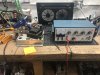
I haven’t hooked it up to speakers yet, just my greened Heathkit ig-5218 audio wave generator, dummy loads, and oscilloscope.

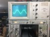
My issue is that at 0.35v rms, I’m getting 2.88w out- any high input and it starts clipping. Even at that, the sine wave looks funky- wider on top than bottom.

Keeping the input on that channel but hooking up the other channel to the oscilloscope, I can bring the input voltage up to 2+v, but it looks funky as hell.

So... I’ve got some problems with input and some funky crosstalk. I don’t know where to start.
3A99806B-5121-431D-AE9B-3592DB49385B.jpeg EC7DCBDA-7904-4F78-8C1F-B9422B108008.png 6E975084-84B5-4981-BFB6-2C19B94BAFE5.jpeg 1299BB16-3FE4-4675-ACD3-66E552EE03B0.jpeg
 
Register to hide this ad
Also, how are the voltages vs the schematic. I can't read it either but I'd expect ~320v at the EL84 plates, 280-320 at the screens and probably ~100v at the plates of the driver tube. Cathode of the EL84 probably in the 12-15v range. If you're way below that, it would explain low power and early clipping.
 
Can’t find the site where I originally found the schematic, but a pdf version is below. May be easier to read.

Will post voltages Thursday evening when I get back to work on it.

Thanks for the assistance!
 

Attachments

Doesn't really look like the rectifier or the cathode resistor value needs to change. I'd expect maybe a tweak to R85 and/or R86 to get voltages right on the screen and driver though.

This is a single ended amp, they're not typically good for more than about 3.5 watts, and much of that will depend on it being into the right load. If this is designed for 4 ohm speakers and you have an 8 ohm load, power output will drop. Honestly you're probably not far off the mark here.
 
  • Like
Reactions: MKG
Also, how are the voltages vs the schematic. I can't read it either but I'd expect ~320v at the EL84 plates, 280-320 at the screens and probably ~100v at the plates of the driver tube. Cathode of the EL84 probably in the 12-15v range. If you're way below that, it would explain low power and early clipping.

Voltage measurements (1 is tube 1, 2 is tube 2) referenced to ground:

Plates: 1) 298.6 2) 290.2
Screens: 1) 280 2) 280
Cathode: 1) 8.87 2) 8.9
 
I did not measure that one. I’ll report back tomorrow evening after I’ve had a chance to measure it.
 
As an alternative approach, all the tube manufacturers used to publish "application notes" for their tubes and they often included typical circuits for SE amps, push-pull amps etc. Those circuits are not difficult to find online. Personally, I would recommend building an amp from scratch using one of those circuits. You could recycle some of the parts from your Dumont Emerson.
 
  • Like
Reactions: MKG
Also worth considering as a model is the DGSE1, schematics can be found on here, but its a comparable single ended EL84 with a 12ax7 driver. Realistically there are only so many ways to actually build such an amp.

either way I suspect you're getting about all its going to give in terms of power.
 
  • Like
Reactions: MKG
Just to clarify-

My current concerns aren’t about it’s output, this is intended to be my first experience with low watt / flea watt amps.

My first concern is that it’s clipping at such a low *input* level. I’m afraid that if I just hook it up to one of my preamps, nudging the volume up a hair from minimum will be full volume and clipping. Maybe I’m over thinking it and should just hook it up?

My second concern is the funky cross talk between the output channels- is this a normal thing that I’m once again over thinking?

Thanks again for the assistance and patience, I’m still working on wrapping my head around some basics.

Edit- my third concern is the funky looking sine wave.
 
My first concern is that it’s clipping at such a low *input* level. I’m afraid that if I just hook it up to one of my preamps, nudging the volume up a hair from minimum will be full volume and clipping. Maybe I’m over thinking it and should just hook it up?
You could just attenuate the signal at the input to the amp, at least while you test it. Or just hook up a preamp and see what happens.
As for the crosstalk, it looks like the cathodes for both channels are sharing one resistor. Its bypass capacitor is what stops the channels from interacting, or tries to. Anyway, the "crosstalk" doesn't happen until the other channel is being seriously overdriven.
 
Last edited:
  • Like
Reactions: MKG
if the concern is the input level, thats probably just how it was designed. Not a ton of feedback and a fair bit of gain makes for a sensitive amp. A lot of things were under 1/2 volt input sensitivity.
 
  • Like
Reactions: MKG
These have an odd screen connection. The OPT's have what look like UL tap connections for the screens, but then they are joined at the screens downstream from the the 3300 ohm resistors making a common screen connections. This then becomes the source for the driver stage B+. Maybe this is the cause of the crosstalk mentioned a few posts above. I would try isolating the screens and deriving the driver supply separately as an experiment.
John
 
  • Like
Reactions: MKG
Edit- deleted some inaccurate info. See below. :P
 
Last edited:
Its actually for hum reduction. The power supply ripple gets fed into the screen out of phase and it cancels the noise out. Roughly the same idea that gets it done in a push-pull amp. Its basically an economy move to get around the need for a choke to better filter the power supply.
 
  • Like
Reactions: MKG
Back
Top Bottom