• The move to the new server is done. There are some software and database maintenance updates in process. This has us passing the hat around to help out. We appreciate any donations. Seriously, even a dollar helps. The payment page may be found here - https://www.audiokarma.org/support.html

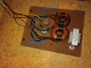
Electro-voice EV-4A Crossover components

Thanks fo all the help.

I have ordered new caps and resistors from Dayton Audio, did not go for Clarity caps because of the price differance. Opted for 4.3uf 250V instead of 4.5uf and 12uf + 1uf for the other 13uf cap. Resistors are 10ohm, 10w.

I have measered the woofers and mid range speakers > woofers measered 7,3Ohm and Mid 6,9Ohm. I have cleaned the 2 pots with contact cleaner and when all the above part arrive I will solder all speaker wires to there respective drivers instead of using the female plugs that are oxcidaded and get the technical stuff done.

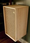
With regards to the cabinets that are in good shape, I will restore them but don´t like the dark color so I will sand them and oil (Trying to get something like the photo in attachement). I dont like the fronts so I will make new fronts like the EV Four ones or like the Wharfedale Dovedale fronts, just one big clouth in light color instead of black.
With regards to the part of the cabinet that you can see if you take off the grills, I was planning to stick black feltro on it so it is nice and black and when drivers are installed it will create a nice seal and it also can act as sound dampening. What do you think about this instead of just black paint?

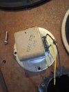
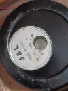
3 more pictures of the drivers, woofer back + tweeter

I will keep this thread updated
 

Attachments

  • 441873119_1595481071309377_5171351601942543818_n (1).jpg
    441873119_1595481071309377_5171351601942543818_n (1).jpg
    99 KB · Views: 17
  • 441573752_1151200022689650_802401782745108614_n (1).jpg
    441573752_1151200022689650_802401782745108614_n (1).jpg
    81.2 KB · Views: 16
  • 441878651_2769681649849429_2674054482968742340_n (1).jpg
    441878651_2769681649849429_2674054482968742340_n (1).jpg
    75.9 KB · Views: 17
  • 1ce5319d9bc2358bac23c7e917201198.jpg
    1ce5319d9bc2358bac23c7e917201198.jpg
    114.7 KB · Views: 18
Update:

I have received all parts today and substituted all caps and resistors.

First I was a little bit disappointed, just listening to some dear straits via youtube then a high res video popped up and WOWWWW.... just one word AMAZING.

I have only one dough here with the mid range speakers that I barely can hear. I have to take them out and connect them to the speaker terminals to see if they are good.

If they are indeed good the problem is in the crossover. What if I take out the resistor at the mid band, would that be a solution to get more out of that speaker or do I have to lower the caps rating? They are fairly big speakers about 18cm or 7inch.

Thanks
 
Update:

I have received all parts today and substituted all caps and resistors.

First I was a little bit disappointed, just listening to some dear straits via youtube then a high res video popped up and WOWWWW.... just one word AMAZING.

I have only one dough here with the mid range speakers that I barely can hear. I have to take them out and connect them to the speaker terminals to see if they are good.

If they are indeed good the problem is in the crossover. What if I take out the resistor at the mid band, would that be a solution to get more out of that speaker or do I have to lower the caps rating? They are fairly big speakers about 18cm or 7inch.

Thanks
Your not going to get high quality audio from You tube videos, you need a streaming service.
only one "dough" ?
 
Just a quick update:

I have bypassed the 13uf cap that is sitting in between the midrange speaker and now I have perfect sound coming out of the midrange. I could not test it at full sound because it is already late here in Europe. And they are hooked up into my Sony Home Theater System that is suppose to be 2x50W in stereo mode but I think this is more 2x20 real watts. I was surprised when I hooked some old book self speakers that are in the family for more then 40 years now. They have some leds that will light up when you turn up the volume. They where hooked up into an Akai amplifier that had 2x26W and I remember that I could crank up the volume and all leds would came on including the last 2, yellow and red ones. With the my Sony that is suppose to be 2x50W all I can see is the first led coming on:(

I will be testing it with my vintage Nikko NR-1219 receiver-amplifier from 1979 in the weekend :)

Next step is restoring the cabinets.
 
The reason you could "barely" hear the midranges where because they were crossed over with a 1 mf cap.
Switch the midrange and tweeters leads around and I am sure you will hear an improvement.
Somebody obviously has been inside these before.
 
The reason you could "barely" hear the midranges where because they were crossed over with a 1 mf cap.
Switch the midrange and tweeters leads around and I am sure you will hear an improvement.
Somebody obviously has been inside these before.
Thanks Rick Owen

So the 13uf cap is meant for the tweeters and the 4,5uf for the midrange?

In the picture green wire goes to the mid range and yellow to the tweeter. So you are suggesting to change those 2? On the back of the speaker the lower pot is for the mid range (green wire) and upper pot is tweeter (yellow wire).

Thanks
 

Attachments

  • 441525029_1576670042901303_8149034684524944791_n.jpg
    441525029_1576670042901303_8149034684524944791_n.jpg
    149 KB · Views: 5
Last edited:
Thanks Rick Owen

So the 13uf cap is meant for the tweeters and the 4,5uf for the midrange?

In the picture green wire goes to the mid range and yellow to the tweeter. So you are suggesting to change those 2? On the back of the speaker the lower pot is for the mid range (green wire) and upper pot is tweeter (yellow wire).

Thanks
Oh my, my bad, I got threads mixed up. I was confused with this thread:


No, the 13uf should go to the midrange and the 4.5 to the tweeters, so sorry.
 
Last edited:
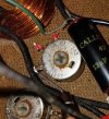
First band looks kinda' orange in the pic above. Though this one shows a more yellow appearance.

View attachment 3212299

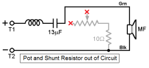
From the traced out schematic, they load the shunt portion of the voltage divider making up tweeter and mid level controls.
[ EDIT -- updated resistors in schematic to 10Ω per revelations in subsequent posts below ]
View attachment 3212958
As suggested above, disconnect at least one lead of the resistor to measure it out of circuit. Replacing [ Edit -- 10Ω ] resistors with something much smaller will reduce output of mid and tweeter.
I have 2 last questions with regards to the schematic.

The only way to get sound out of the midrange is by taking out the 13uf capacitor. Fideling with the l-pad of the midrange will not give any change in sound. I have some good hours of listening time on the speakers (crossover without the 13uf in place, 1 peace of speaker wire instead). The speakers sound great but I think something is off and think it has to do with the mid range speaker.

1:
How can I wire the mid range speaker without the pot in place?

Would that be:
Copper coil - 13uf - 10Ohm res - speaker +
Speaker ground goes direct to - poll of the speaker.

2:
How can I increase the bass a little bit? (Placing a capacitor between coil and connecting it with the ground poll). So that would be + poll - copper coil - capacitor connects to - poll - speaker +
What would be a good value for the above capacitor to start with?

The speakers have a very tight bass but I would like to have it more BOOM.

Thanks for all the help..
 
How can I increase the bass a little bit?

The speakers have a very tight bass but I would like to have it more BOOM
Those are not the original woofers, they look like pro-sound drivers, you won't get much bass out of them in a small enclosure like the EV 4A
 
@jsengxx , you'd get more bass out of these...

 
The only way to get sound out of the midrange is by taking out the 13uf capacitor. Fideling with the l-pad of the midrange will not give any change in sound. I have some good hours of listening time on the speakers (crossover without the 13uf in place, 1 peace of speaker wire instead).
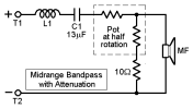
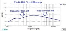
Running those mids without the series capacitor could be bad for their health. The inductor and capacitor in series make up a band-pass filter to isolate the frequency range fed to the midrange driver. Value of the capacitor determines where low frequency rolls off. Inductor value defines where high frequency roll-off occurs.

Here's an example of a midrange circuit configured like yours ...
E-V 4A mid bandpass.png
... and what response would generally look like in simulation:
EV 4A mid mockup.JPG

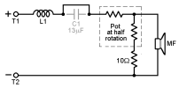
Bypassing that series capacitor would eliminate low frequency roll-off
E-V 4A mid BP cap.png

EV 4A mid sans cap.JPG
Which means the midrange receives same low frequencies as fed to the woofer. Could take a beating due to excursion limit alone.

How can I wire the mid range speaker without the pot in place?

Would that be:
Copper coil - 13uf - 10Ohm res - speaker +
Speaker ground goes direct to - poll of the speaker.
That would eliminate the pot though keeping the shunt resistor across the midrange. Easier yet to bypass the whole resistive circuit. Just remove 13µF cap lead and green wire from the pot, then connect the removed leads together.

E-V 4A BP mid control.jpg

Which changes the midrange circuit to this:
Resistive ckt removed.png
All parts can remain in place to reconnect later if desired. Although circuit simulation suggests that midrange level won't be any higher than minimum attenuation setting of the pot.

EV 4A Mid Atten.JPG
It does show midrange response peak narrowed from total resistance of pot plus the 10Ω resistor in shunt across the mid driver when set to minimum attenuation. That becomes narrower still if pot is removed and only the resistor left across the mid (not shown in graph above).

Another thing you might try is reversing polarity of the midrange connection wires at the driver. It's not unusual to see large nulls occur in multi-driver systems requiring one or more drivers to be wired in reverse phase of others. Simulation suggests this very thing might occur with the EV-4A mid circuit.

midrange phase inversion.png
 
Running those mids without the series capacitor could be bad for their health. The inductor and capacitor in series make up a band-pass filter to isolate the frequency range fed to the midrange driver. Value of the capacitor determines where low frequency rolls off. Inductor value defines where high frequency roll-off occurs.

Here's an example of a midrange circuit configured like yours ...
View attachment 3247456
... and what response would generally look like in simulation:
View attachment 3247458

Bypassing that series capacitor would eliminate low frequency roll-off
View attachment 3247462

View attachment 3247460
Which means the midrange receives same low frequencies as fed to the woofer. Could take a beating due to excursion limit alone.


That would eliminate the pot though keeping the shunt resistor across the midrange. Easier yet to bypass the whole resistive circuit. Just remove 13µF cap lead and green wire from the pot, then connect the removed leads together.

View attachment 3247688

Which changes the midrange circuit to this:
View attachment 3247695
All parts can remain in place to reconnect later if desired. Although circuit simulation suggests that midrange level won't be any higher than minimum attenuation setting of the pot.

View attachment 3247702
It does show midrange response peak narrowed from total resistance of pot plus the 10Ω resistor in shunt across the mid driver when set to minimum attenuation. That becomes narrower still if pot is removed and only the resistor left across the mid (not shown in graph above).

Another thing you might try is reversing polarity of the midrange connection wires at the driver. It's not unusual to see large nulls occur in multi-driver systems requiring one or more drivers to be wired in reverse phase of others. Simulation suggests this very thing might occur with the EV-4A mid circuit.

View attachment 3247724
Thanks for the above info.

I did the above changes to mid and tweeters, just took out the l-pods, and put back into the crossover the 13uf cap for the mid range driver. I did not like the sound of the bypassed 13uf cap, it was like the mid range drivers were screaming at you but now when I have the 13uf cap back, I, again can barely hear the mid range drivers.

What is causing this issue? Do I have to change the value of the cap? Higher or lower?

Thanks
 
In the specs for this speakers I could find that the mid range is going from 400 - 2500HZ.

If I use the below website to calculate the uf for the mid range I get about 50-58uf for the capacitor (7.3-8ohms).


Would this be correct taking into account that the original cap is 13uf, 50-58uf? This is a big difference. Would this be the reason why I don´t get sound, or low sound, out of the mid range speakers?
 
Back
Top Bottom